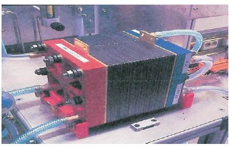
Figure1. Example of a PEM Fuel Cell with the following operational specifications.
Research into renewable energy sources has previously lacked sufficient investment. However, emphasis has now shifted and funding is being made available in a proactive manner by various governments eager to encourage renewable energy technology and reduce carbon taxes. Fuel Cells offer a realistic, sustainable and clean alternative energy option for stationary and mobile applications. Hydrogen and fuel cell technologies are recognised by many as possible long term energy solutions, but to-date, have failed to make an impact on the energy market. This is due to a number of key reasons, some of which include efficiency, scale, accessories and power output. For example, applying fuel cells to small telecommunication components requires the applications of Micro and Nanotechnology, which have yet to be perfected to make them long lasting and cost effective. This paper focuses on the design, engineering and development of a new Alkaline Fuel Cell outlining its capabilities and limitations for satisfying future energy needs in terms of its long term operation in air.
For the last fifty years, research into renewable energy sources has lacked sufficient investment. But now it seems the emphasis has shifted and funding is being made available in a proactive manner by various governments eager to encourage the commercialisation of renewable energy technology and reduce carbon taxes. The fuel cell has been in existence for over a hundred years and still there are numerous problems to be resolved before commercialisation and mass production can be realised. William R. Groves (1811-1896) a barrister in Swansea discovered the principle of the fuel cell while conducting electrolysis experiments in 1842. Groves generated electricity by reverse electrolysis, from a four cell gas chain and used the generated current to split water into hydrogen and oxygen in an upper cell [1]. Some hundred years later Francis Bacon (1904-1992) took fuel cells from the research stage and produced an Alkaline Fuel Cell (AFC) that became part of the NASA space program and provided the main power source for the Apollo space missions, clocking up thousands of service hours [2], [3].
The main attraction of the Alkaline Fuel Cell to the space program was its high thermal efficiency (approaching 70%), the use of non noble metals as part of its construction, making it considerably cheaper than its rivals and low hydrogen and oxygen consumption with the only by-products being heat and water, the latter being used for drinking purposes reducing onboard weight [4]. As part of this program the alkaline fuel cell powered 106 missions and clocked up more than 82,000 service hours for NASA [5]. All this development should have spelt the beginning of the hydrogen economy but with cheap and abundant fossil fuel readily available and fuel cells still experiencing technical difficulties the opportunity to switch to a renewable, sustainable, and environmentally friendly energy alternative was set aside. As the space program pioneered most investment into fuel cell research, when NASA switched allegiance from the alkaline fuel cells to the dry electrolyte Solid Polymer Fuel Cell (SPFC) developed by General Electric, American interest in alkaline fuel cell technology ceased. Later in the 1990's Ballard Technologies with its newly named Proton Exchange Membrane Fuel Cell (PEMFC) scored great success in financing its technology development program and attracting automotive industries as strategic partners. This left only a few players remaining in the AFC field world wide, mainly based in Europe[6]. However, the benefits of the Alkaline Fuel Cell originally realised by NASA, including low temperature operation, high efficiency, low consumption and cheaper construction are important factors for promoting commercialisation of alkaline fuel cells in today's cost effective market.The conventional view is that alkaline fuel cells are expensive and cannot be operated in air due to carbonate formation and poisoning by impurities that limit cell and electrode life[7], [8]. Additionally, problematic issues such as dilution of the electrolyte due to water generation during the reaction, material stability in concentrated, separator materials and the perceived necessity of having ultra-pure hydrogen and oxygen gases present challenging technological barriers to implementing AFC's in real world scenarios. Thus, to date, AFC's have been used only in very specialized applications. This paper presents results associated with the design, engineering, evaluation and testing of novel AFC technology developed to solve some of the main problems associated with long term operation of AFC's in air.
A fuel cell is a device that generates electricity by a chemical reaction. Every fuel cell has two electrodes, one positive (the anode) and one negative, (the cathode). The reactions that produce electricity take place at the electrodes. Every fuel cell also has an electrolyte, which carries electrically charged particles from one electrode to the other, and a catalyst, which speeds the reactions at the electrodes. Hydrogen is the basic fuel, but fuel cells also require Oxygen. One great appeal of fuel cells is that they generate electricity with very little pollution because much of the hydrogen and oxygen used in generating electricity ultimately combines to form water. A single fuel cell generates a tiny amount of Direct Current (DC) electricity. In practice, many fuel cells are usually assembled into a stack. Cell or stack, the principles are the same. There are several kinds of fuel cells, and each operates a bit differently depending on the fuel and oxidant, direct or indirect fuelling or type of electrolyte and temperature of operation. But in general terms, hydrogen atoms enter a fuel cell at the anode where a chemical reaction strips them of their electrons. The hydrogen atoms are ionised and carry a positive electrical charge. The negatively charged electrons provide the current through a circuit. If Alternating Current (AC) is needed, the DC output of the fuel cell must be routed through a conversion device, i.e. an inverter. Oxygen enters the fuel cell at the cathode and, in some cell types combines with electrons returning from the electrical circuit and hydrogen ions that have travelled through the electrolyte from the anode. In other cell types the oxygen picks up electrons and then travels through the electrolyte to the anode, where it combines with hydrogen ions. Fuel cells are typically low voltage, high current power sources. Cells are stacked together to create the required current and voltage rating. For example, Figure 1 shows a PEM (Proton Exchange Membrane, also called Polymer Electrolyte Membrane) fuel cell comprising 20 cells with a 10V, 50A, 500W combined rating. A PEM fuel cell uses a simple chemical reaction to combine hydrogen and oxygen into water, producing electric current in the process. It operates like electrolysis in reverse: Hydrogen and oxygen inputted via the anode and cathode of the cell respectively results in the production of electrical energy and formation of water as an extract [9].
No. of Cells: 20
2 Cell Area: 100cm
DC- Open-Circuit Voltage: 18V
DC- Power: 550W (Air) 10...12V
Heat Dissipation: 0...500W
Operation Temperature: >0 to 60°C
Nominal Operational Point: 55°C, 25°C TP Cathode
Figure1. Example of a PEM Fuel Cell with the following operational specifications.
A fuel cell converts chemical energy into DC electrical energy. This can be achieved by various ways and means depending on the fuel and oxidant, direct or indirect fuelling or type of electrolyte and temperature of operation. Fuel cells are categorised as high or low temperature cells and this dictates their suitability for various applications, stationary, transport or heat/plant.
The electrolyte used in a cell can be either solid or liquid. For temperatures below 100o C, aqueous acid, alkaline or a solid electrolyte may be used. Between 100o C and 200o C it is necessary to use highly concentrated solutions of acids such as phosphoric acid. Between 200oC and 400oC, one may use molten alkaline hydroxides and from 600o to 1000o C molten carbonate or salt mixtures may be used. Above 1000o C solid electrolytes can also be used. The very popular Proton Exchange Membrane (PEM) cell employs a solid electrolyte that allows positively charged ions to travel unimpeded across the polymer membrane while rejecting negatively charged ions forcing them to flow through an external circuit in the form of electrical current. The preference for acidic or alkaline electrolytes is dependant on the desired application, for a mobile situation (e.g. buses, trucks, cars) alkaline electrolytes would be suitable but the acidic PEM cell is the one most vehicle manufacturers involved in fuel cell research prefer. Advantages of using an alkaline electrolyte compared to an acidic electrolyte are that electrode materials other than noble metals (platinum) can be utilised. Other cell materials that form part of the cells casing and construction can also be produced from inexpensive material with less risk of aggressive attack, these are important factors to the longevity and cost of the fuel cell. Also oxygen reduction reaction is faster in alkaline solutions than in acids.
The principles associated with the operation of an Alkaline Fuel Cell (AFC) is shown in Figure 2. This cell utilises the migration of Hydroxyl ions (OH-) from the cathode to the anode to create a reaction. At the anode the hydrogen gas (H2) combines with the hydroxyl ions (OH-) to form water (H2O) and electrons (e-). Because the electrons cannot pass through the electrolyte they are forced out at the anode supplying current to external loads. Water formed at the anode then migrates back to the cathode where it joins up with oxygen (O2) and returning electrons to regenerate the hydroxyl ions (OH-) and the cycle repeats itself. Most reaction water leaves at the anode (H2 ) side but a small amount is removed via the electrolyte causing the electrolyte's molar concentration to be weakened affecting the cell output. The remedy for this is to periodically replace the Potassium Hydroxide electrolyte.
Oxidation at Anode: 2H2 +4OH → 4H2O + 4e
Reduction at Cathode: O2 + H2O + 4e→ 4OH
Overall Reaction: 2H2 + O2 →2H2O
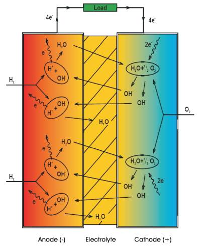
Figure 2. Operation of the Alkaline Fuel Cell
The Polymer Electrolyte Membrane or Proton Exchange Membrane refers to the solid acid electrolyte used. As hydrogen gas (H2) enters the cell at the anode side it comes into contact with a precious metal catalyst and breaks down into protons (H+) and electrons (e-). The catalyst is a substance usually platinum that accelerates a chemical reaction. The protons can pass unimpeded through the thin plastic membrane while the electrons travel in the form of current to supply the external loads before returning to the cell at the cathode. The protons that have diffused through the membrane reunite with the electrons and react with the oxygen fed in at the cathode to produce water (H2O). This process produces no pollution and the only by-products are water and heat.
Oxidation at Anode: 2H2 → 4H+ + 4e -
Reduction at Cathode: O2 + 4H+ + 4e- → 2H2O
Overall Reaction: 2H2 + O2 → 2H2O
The PEM fuel cell is finding most favour with Motor Manufacturers and is believed in some quarters to be most suitable for transportation and small stationary applications. Compared to other types of cell the PEM generates more power for a given volume or weight of fuel cell. There is also the added advantage that it uses air as opposed to pure oxygen and does not require a corrosive fluid to operate [10]. The Canadian company Ballard Power Systems and the American company UTC Fuel Cells are acknowledged as two of the leading companies in the industry and both are developing PEM fuel cells for the mass market, especially the transportation sector. Other important US companies include Fuel Cell Energy, which is developing large-scale fuel cell power plants and Plug Power, which is developing smaller units to power residential and commercial premises, [11]. The commercial potential of the PEM fuel cell and the continued investment has lead to the development of ion conducting plastic film membranes that generate electric current more easily, operate across a broader temperature range and cost less than incumbent materials, which are mainly sulfonated fluoropolmers[12]. This allows for a compact, low cost and quick responding cell technology more suited to the various application demands of industry. However some of the main problems that still impair the dominance of the PEM fuel cell are Carbon Monoxide poisoning, affecting the long-term performance of the membrane. The PEM fuel cell requires pure hydrogen as a fuel and therefore is not suited to on-board reforming of hydrocarbons (natural gas, gasoline etc.). Also it's use of precious metal catalysts especially platinum which is rare and costly. PEM fuel cell technology has been targeted for transportation applications because it operated efficiently on pure hydrogen with the result being zero emissions. But converting from a Carbon based economy to a Hydrogen economy is a future aspiration, and realistically reforming of fossil based fuels to extract hydrogen would be required in the interim to bridge the gap.
The DMFC are relatively new and similar to the PEM cell in that it uses a polymer membrane as an electrolyte. However, in the DMFC the anode catalyst draws the hydrogen from the liquid methanol, eliminating the need for a fuel reformer. The liquid Methanol is oxidized in the presence of water at the anode and produces CO2 , hydrogen ions and electrons. The hydrogen ions pass through the membrane and the electrons travel through the external circuit as current, reuniting to react with the oxygen from the air to form water at the anode and complete the circuit, [12]. Initially the DMFC was ignored because of its high catalyst costs (platinum), fuel crossover effect, poisonous fuel, low efficiency and power density problems. But it now seems that new technology has resolved these matters and interest in the DMFC has resurfaced for very small to mid size applications like laptops, cellular phones and motor vehicles, because it offers low temperature operation without the need for a reformer.
The PAFC is considered the first generation of modern fuel cells and was one of the first to be commercialised. Its typical use is stationary power generation and also to power large vehicles like city buses. As the name suggests the electrolyte is liquid phosphoric acid (H3 PO4) at nearly 100% concentration and it is most conductive at a temperature of 150 to 200o C. It operates similar to a PEM fuel cell, as the hydrogen (H2) enters the cell at the anode, the catalyst causes it to split into protons (H+) and electrons (e-). The protons migrate through the electrolyte to the cathode side where they combine with the electrons from the external circuit and oxygen (O2 ) from the air to form water and another by-product, heat[13].
Solid oxide fuel cells use a solid ceramic electrolyte and operate at very high temperatures. The high temperature operation is considered an advantage because of the cells flexibility to use more types of hydrocarbon fuel (natural gas, diesel, gasoline, alcohol, coal gas) be tolerant of impurities and use inexpensive catalysts, but a disadvantage in that high temperatures enhance the breakdown of cell components. Because of its high efficiency output, 60% approx., the SOFC is mainly used for power generation with a potential also to power vehicles [14]. The solid electrolyte structure of the SOFC is impervious to gas crossover from one electrode to another, with the charge carrier being the oxygen ion (O-2). At the cathode the oxygen molecules from the air are split into oxygen ions with the addition of four electrons. The oxygen ions are conducted through the electrolyte and combine with the hydrogen at the anode, releasing four electrons. The electrons exit the cell as current to supply the external circuits and return to the cathode to continue the cycle. The by-products are heat and water that exits the cell on the anode side.
MCFC are high temperature fuel cells operating at temperatures in excess of 650o C. This implies high fuel to electricity efficiencies of up to 60%, increasing to 85% if the waste heat is utilised. The MCFC uses a molten carbonate salt mixture as its electrolyte; the two commonly used compositions are lithium carbonate and potassium carbonate, or lithium carbonate and sodium carbonate. The mobility of the Carbon Trioxide ion is dependent on the conductive mobility of the melted salt (a liquid at 650o C). At the anode a reaction occurs between hydrogen and carbonate ions (CO32- ) that have migrated across the electrolyte from the cathode that produces water, carbon dioxide (CO2 ) and electrons. The electrons are routed through the external system as current and return to the cathode to combine with oxygen (O2) and carbon dioxide (CO2 ) to produce carbonate ions to continue the process. The bi-products of producing electricity in this fashion are water and heat with carbon dioxide being collected at the anode exhaust and mixed with the cathode feed stream [15].
Research at Dublin Institute of Technology (DIT) has centred on developing alkaline fuel cell engineering with a view to promoting this technology and steering it towards commercialisation. In conjunction with a German industrial partner, Gaskatel GmbH, DIT has built a single cell test bed for education and research purposes to enhance its research potential in this area and assist in refining Gaskatels alkaline fuel cell and system. In an alkaline cell, fuel oxidation occurs at the anode. The single fuel cell unit that has been developed has two hydrogen electrodes made of Raney-nickel which have a high catalytic activity at low temperature for hydrogen oxidation and at the cathode oxidant reduction is accomplished by two oxygen electrodes made of silver. The supply for the gases and electrolyte are situated at the bottom of the cell and the exit for both gases and the electrolyte are at the top of the cell. This allows the cell to benefit from the fact that both hydrogen and oxygen will flow freely up through the cell of their own accord. The gases also move quicker through the cell on start-up, which helps to expel any trapped bubbles, inert gases and reaction water that may lodge in the cell on shutdown and re-start.
The cells output is most efficient at a constant o temperature of 55oC. As part of the cells construction two heating elements are fitted between the positive and negative poles of the cell and connected in series (24 VDC, 1A) to speed up the heating process. This method of heating the cell is only effective if the electrolyte is immobile, when electrolyte circulation commences the cell temperature drops quickly and drastically affecting the cells potential. The conclusion gathered from this is that the mobilisation of the electrolyte, although beneficial should be controlled, becoming more intermittent than constant. The temperature of the cell is monitored to prevent damage of overheating by a Pt. 100 resistor also positioned inside the cell in close proximity to each heating element.
The gas pressure within the cell also requires regulating and monitoring at a set 0.5 bar above atmospheric pressure to prevent cross-over between the electrolyte and the gas. When the electrodes are being constructed a two-pore system is created, the hydrophobic pores through which the gas flows and the hydrophilic pores through which the electrolyte flows. Capillary forces keep the electrolyte in the small pores when an over pressure of the gas with respect to the electrolyte is applies (as referred to above). In the alkaline fuel cell the gas diffused porous electrodes are very important and the contact zone where reactant, electrolyte and catalyst meet is called the three-phase zone[16].
The cell has one active separator and two passive separators. A thin porous plastic film or active separator is critically used to separate the anode and cathode electrodes from each other. This separator also facilitates the migration of the hydroxyl ion from the cathode to the anode and the water return in the opposite direction. The passive separators only separate the KOH and gas chambers from each other. In alkaline fuel cell systems, the preferred electrolyte is usually the aqueous potassium hydroxide (KOH), which has a higher conductivity than most other alternatives. Sodium hydroxide (NaOH) was envisaged as a potential option but on balance its performance characteristics were less interesting than that of KOH, and the cost advantage was not really that important because the KOH electrolyte can be used for a longer time in the fuel cell so that its cost to the overall cost is almost negligible[17].
Conventional wisdom in nearly all the Fuel Cell (FC) literature states that alkaline fuel cells are expensive and cannot be operated in air due to carbonate formation and poisoning by impurities that limit cell and electrode life. Indeed, perhaps in part because of this, AFC work is conspicuously missing from a range of research programs at least in the EU. Additionally, problematic issues such as dilution of the electrolyte due to water generation during the reaction, material stability in concentrated, hot KOH, asbestos separators and the perceived necessity of having ultra-pure hydrogen and oxygen gases present challenging technological barriers to implementing AFC's in real world scenarios. Therefore, to date, AFC's have been used only in very specialized applications.
After initial AFC development in the 1960's (AFC's powered some systems and provided water on the Apollo manned space missions) the end of the oil crisis at the beginning of the 1980's marked the start of a hiatus in interest in fuel cells. In the mid to late 1990's, a resurgence in the development of FC's as an alternative energy source was punctuated by significant venture capital investment, both in Europe and North America. It is generally believed that today's batteries will not provide the needed energy density for mobile devices such as music players, computers, telephones, motor vehicles, moving machinery and electric wheelchairs. It is predicted that there will be a $2bn market for portable power cells by 2011. However the interest in alkaline fuel cells was low as the Polymer Electrolyte Membrane Fuel Cell (PEMFC) seemed to be the superior system, partly for the reasons given above.
In the last two years, significant progress has been made in low cost, long term AFC operation using technology developed at Gaskatel, GmbH in Kassel, Germany in collaboration with an international team of researchers. The objectives of this work were fourfold:
(i) To operate an AFC with air instead of pure oxygen; (ii) To find a solution for the classic CO2 problem; (iii) To remove the reaction water that dilutes electrolyte as the reaction proceeds; (iv) To develop technology so that long term, maintenance free operation of a simple, self regulating AFC system was cost effective and commercially feasible.
The functional principle of fuel cells is based upon the controlled electrochemical reaction of hydrogen and oxygen with the purpose of using the electrical produced by the reaction: 2H2 + O2 → 2H2O. The gases are brought into two sides of the fuel cell that are separated by a semipermeable membrane and the redox reaction occurs at the electrodes, where H+ and OH- ions respectively that recombine to form water and generate electrons. The overall reaction can be split into the two half reactions taking place at the anode and the cathode. The exact details of the balanced half reaction equations depend on the type of electrolyte being used, but in concentrated KOH the reactions are given below:
In the Fuel Cell in Figure 3, the hydrogen electrode - (anode) hydrogen gas reacts with OH- to form water, generating the electrons used in the reduction of oxygen at the cathode:
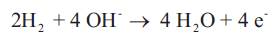
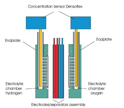
Figure 3. Alkaline Fuel Cell Assembly
At the oxygen electrode (cathode), oxygen gas reacts with water to form OH-
The fuel cells constructed for these tests utilised nickel as the catalyst for the hydrogen electrode and silver for the oxygen (air) electrode. Both electrodes were manufactured using a rolling process. For the operation with air in place of bottled oxygen, the gas supply system had to be re-adjusted to the new conditions. If air is used instead of oxygen the gas flow through the cell has to be considerably higher (air has approximately 21 % oxygen) and a larger compartment was fabricated.
If an AFC is operated with air instead of pure oxygen, conventional wisdom suggests that the CO2 will dissolve and form carbonate ion in the potassium hydroxide solution (KOH). The CO2 contained in the air dissolves into the KOH solution and forms the less soluble potassium carbonate according to the equation:

After reaching the saturation point (about 7 Molar in K2CO3 at room temp and measured in this work), the potassium carbonate precipitates. The electrodes in an AFC are Gas Diffusion Electrodes (GDE), and the structure can be compared with a micro-porous sponge. It has been quite sensibly believed that the pores would be clogged by the carbonate generated thus blocking the reaction and rendering the system nonfunctional.
As stated above, to operate with air in place of bottled oxygen, the gas supply system had to be redesigned. If air is used instead of oxygen the gas flow through the cell has to be considerably higher. In addition, many changes had to be made to develop the fuel cell and adapt it to the demands of operation with air including designs for an expanded gas compartment and to prevent the drying up of KOH and blocking of the air inlet.
Another unrelated problem is that the water created in the reaction dilutes the electrolyte and lowers its conductivity, reducing system efficiency to the point where it eventually ceases to run effectively. Apart from that, the total electrolyte volume increases as water is generated which would eventually cause an overflow of the storage vessel or cell. These and other factors must be considered to make a low cost and reliable AFC cell system.
Following half-cell testing, electrical characterisation of electrodes and electrode selection, fuel cells were manufactured and tested. The following situations were investigated and are discussed below: (i) Tests under real operating conditions with air containing CO2 ; (ii) Removal of reaction water under real operating conditions; (iii) Variation of the electrolyte (KOH, K2CO3 , KHCO ) during operation; (iv) Long-term test of an oxygen electrode and a fuel cell with air.
The objectives of the tests were to understand the operation of an AFC operating in air instead of oxygen and consider the following:
Find a solution for the CO2 problem
Find a solution to get rid of the reaction water
Development of an AFC system for long term operation.
Enable a maintenance free operation of the system
The methods adopted involved: (I) Testing electrodes in a half cell including the selection of appropriate electrodes, their characterisation and variation of the electrolyte (KOH, K2CO3, KHCO3); (ii) Testing the AFC under real conditions with air containing CO2 for the removal of reaction water; (iii) Gas analysis with the gas chromatograph including information about the fate and behaviour of the CO2; (iv) Electrolyte analysis by titration to obtain information about the formation of carbonate.
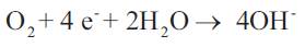
To understand the fate and behaviour of the CO2 gas in solutions representative of those in alkaline fuel cells, gas chromatography was used as seen in Figure 4. By bubbling the feed gases through a fritted wash bottle filled with various solutions, relative amounts of gas in the input and output streams were quantified. From the results given in Figure 4, we can conclude that carbon dioxide was indeed absorbed both by the 7M KOH solution as well as a solution rich [3.5M] in carbonate ion, as expected. However, as Figure 5 shows, despite the high levels of carbonate ion in solution, were able to demonstrate that the sensitive oxygen cathode would run for 5400 hours with insignificant decrease in operational voltage and current. Carbonate ion in solution was quantified by titration. After 1000 hours of operation in a half cell at a current of 50 mA/cm², the carbonate concentration of the KOH solution was 50 g/l. This is far below the solubility limit of K2CO3 in 7 mol/l KOH. We can therefore conclude that during the experiment, saturation did not occur and no carbonate precipitated to clog the electrode pores. Another experiment in which the cell electrolyte was artificially made to be 3.5M in potassium carbonate in addition to the normal 7M KOH, was performed. Over the experiment duration the carbonate content increased from 475.9 g/l to 497.7 g/l. Both values are clearly below the solubility limit of 1135 g/l (at 25 °C) for K2CO3 in water further supporting the notion that carbonate formation in these type of AFC's is not an issue for operation in air. It was instead found, by pre-soaking the electrodes in separate nearly saturated solutions of potassium carbonate and KOH as well as the mixture, that when re-immersed, the carbonate soaked electrode operated while hydroxide crystals plugged the pores and damaged the electrode, presumably by corrosion. The results of Figure 5 mean that for the combination of electrodes used in Gaskatel's Eloflux cell, carbonate ion generation does not poison or destroy the cell performance.
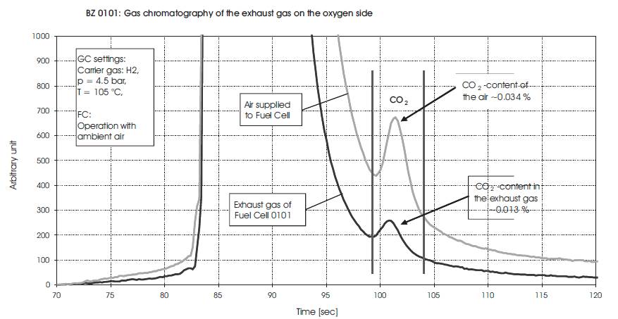
Figure 4. Analysis of CO2 depletion relative to the input.
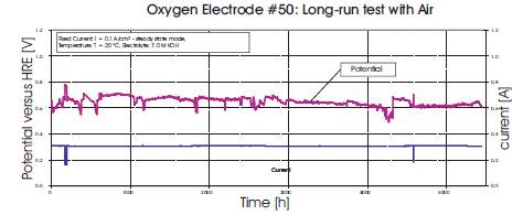
Figure 5. Results of using an Ag Cathode run for more than 5400 hrs in CO2 containing air.
In the exhaust gas, the CO2 concentration was lower than in the feed gas. Carbonate was created in the electrolyte, but only a small, reversible loss of performance could be detected during operation with air as well as during operation with pure oxygen. We conclude that the creation of carbonate in the liquid KOH solution did not deteriorate the performance of the fuel cell. Deterioration could be caused by a bad mass transport or/and by corrosion due to the increase of KOH concentration. In Figure 6, an AFC assembled from tested electrodes ran for nearly 500hrs before being stopped and there was no indication that it would not continue for much longer. Such longer term tests are also ongoing and the subject of future work.
Figure 6. AFC Operation in Air for 500hrs
For an AFC to operate efficiently, the concentration of the hydroxide electrolyte has to be maintained despite dilution by the water generated in the reaction. To passively remove reaction water as the cell operated, attempts were made to remove water via airflow at the oxygen electrode at a variety of temperatures as illustrated in Figures 7 and 8. For these experiments the weight increase of the electrolyte caused by the water of the reaction was measured. The experiments were conducted at temperatures of 30 °C, 40 °C and 50 °C in long term measurements with unfiltered air. The cell was loaded with a fixed current I=3.0 Amps. Figures 7 and 8 show two sets of data for this experiment, one taken at 40oC and one at 50oC. The results are presented graphical form with a line indicating the theoretical weight increase of the KOH solution due to water formation and calculated by using Faraday's Law: m=(IMt)/(zF) where m is the mass in kg, I is the current in Amps, t is time in second, M is molar mass in kg/kmol, z is the number of electrons and F is the Faraday constant (96485 C/mol) If the measured weight increase is lower than the theoretical (calculated) weight increase, we can assume that the water of reaction was extracted by the air flow. We found that with the current experimental setup it was not possible to remove all the water of reaction via air flow through the gas compartment of the oxygen electrodes. One problem with this cell construction and experimental configuration was that the air flow dried up the KOH solution and the air inlet became blocked by solid KOH. However, operating at 50 Celcius, significant amounts of the water generated was removed, but in order to utilize this technique of water removal, reengineering of the cell is necessary to prevent damage and blockages.

Figure 7. Water Weight Increase in Electrolyte at 40oC
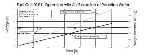
Figure 8. Water Weight Increase in Electrolyte at 50oC and 3A
In conclusion, we have demonstrated that it was possible to run an oxygen electrode for more than 5000 hours with air containing normal levels of CO2 . With a constant current density of 100 mA/cm² there was a decrease of potential of about 10%. The decrease was reversible by changing to fresh electrolyte solution. We have demonstrated that by modifying the ingredients of the electrode it is possible to manufacture electrodes that are suitable for operation with CO2 containing air for long term operation. Further, water of reaction was partially removed via airflow on the oxygen electrode and careful cell design in the future may permit this technique to maintain electrolyte concentration at optimum levels for operating an AFC.