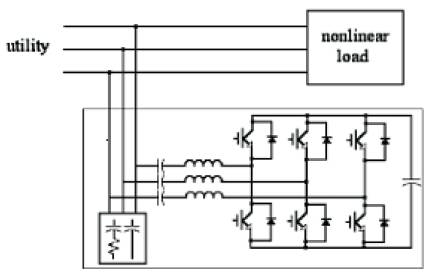
Figure 1. System Configuration of the Hybrid Active Power Filter
In this paper, a new hybrid active power filter using a voltage-source power converter with a series connected inductor and capacitor set is proposed. The power converter is controlled to produce a voltage proportional to the harmonic component of the load current. The compensating current flows into the power feeder via the series connected inductor and capacitor set and suppresses the harmonic currents generated by the nonlinear loads. The advantages of the proposed filter are low voltage rating of dc capacitor and power switches, smaller inductor, and low Electro Magnetic Interference.
Power electronics and microelectronics have become two technologies that have considerably improved the quality of modern life, allowing the introduction of sophisticated energy-efficient controllable equipment to industry and home. Such modern computer and electronics based equipment, rapidly spreading in industrial and domestic applications, is susceptible to many types of disturbances in addition to actual interruptions so that power quality problems have attracted more and more attention. The higher power quality demand more advanced technology.
The developments of modern power electronic applications, such as active filters and active compensators, provide effective methods to minimize undesirable power quality effects for example reactive power, unbalance and harmonics [4]. The harmonic current may pollute the power system causing many problems such as increase in losses and consequent heating of transformers and rotating machines, higher order harmonics lead to increase in frequency dependent, voltage quality degradation, malfunctioning of protective devices, malfunctioning of medical facilities, and inductive inter ference with the neighbouring communication. [6]. Harmonic currents are results of non-linear loads that require currents other than sinusoidal. The harmonic current that occurs in power systems can be suppressed by using a passive or an active power filter or a combination of the both [2, 3]. Conventionally, the simplest method of harmonic filtering is with passive filters. They use capacitors and inductors. They have the advantages of simplicity, reliability, high efficiency and low cost. But the disadvantages of the passive filter are,
Active Filters are the new trends in harmonic filtering technology. They make use of state of the art power electronic switches and advanced control techniques. The basic principle of operation of an active Filter is to inject a suitable non-sinusoidal voltage and current into the system in order to achieve a clean voltage and current waveforms at the point of filtering [1]. Hybrid filters combine both passive and active filters to retain their advantages without any of their disadvantages. The active filter in series with parallel passive filter is known as “HYBRID ACTIVE FILTER”. The passive filter is generally tuned th th for the 5 and 7 harmonic components. The active filter improves the passive filter performance and protects it from resonance and harmonic amplification problem. The VA rating of the active converter is reduced as much as possible in order to reduce the overall cost, EMI and losses [5].
In this method, the harmonics in the utility current are suppressed by injecting a current that is equal and opposite of the load harmonic component alone. For this, a compensating voltage that is proportional to the load harmonic current is generated using a VSI. This voltage injects a current, equal and opposite to load harmonic current, whenever the load draws the harmonic current. The inductor in the series connected inductor and capacitor set is used to filter the switching ripple of the power converter and hence it is very small. The capacitor in the series connected inductor and capacitor set is used to supply a fixed reactive power. The rating of the inductor and capacitor set used in the proposed filter is small than the conventional method. The filter is implemented for a power system of 25 KV,10 MVA,50 Hz supplying a nonlinear load (controlled rectifier).
The system configuration of the proposed hybrid active power filter is shown in Figure 1. It consists of a power converter (voltage source inverter) in series with an inductor and capacitor set. The power electronic device used in the filter is IGBT. It is fed by a dc power capacitor. The voltage mode control is used to control the voltage source converter.
Figure 1. System Configuration of the Hybrid Active Power Filter
Figure 2 shows the equivalent circuit of the proposed active power filter. It consists of two voltage sources, one is the utility (V ) and the other is the power converter (V ). The s ah compensating voltage generated by the power converter is a dependent voltage source whose voltage depends on the harmonic components of the load current. Z is the impedance of the series connected LC inductor and capacitor set. IL is the load current.
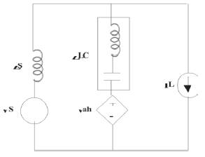
Figure 2. Equivalent Circuit of the Hybrid Active Power Filter
The equivalent circuit of the proposed active filter can be further divided into the fundamental frequency equivalent circuit and the harmonic equivalent circuit.
Figure 3 (a) shows the fundamental frequency equivalent circuit. The compensating voltage generated by the power converter only contains harmonic components. Under the fundamental frequency the power converter acts as a short circuit. If the frequency is lower than the tuned frequency, the series connected inductor and capacitor set is capacitive. Hence series connected inductor and capacitor set does the fixed reactive power compensation. The compensated reactive power can be approximated as,
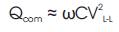
Figure 3(b) shows the harmonic frequency equivalent circuit. The series connected inductor and capacitor set is inductive if the frequency is higher than the tuned frequency. The switching frequency of the power converter is significantly higher than the tuned frequency of the inductor and capacitor set. As a result, the series connected inductor and capacitor set acts as an inductor to filter the switching frequency of the power converter. The desired compensating voltage for suppressing the load harmonic current can be derived as,

Where, ILH is R.M.S. value of the harmonic component of Lh the load current.
ZLC is the impedance of the series connected inductor and capacitor set.
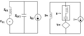
Figure 3(a). Fundamental Frequency Equivalent Circuit Figure 3(b). Harmonic Equivalent Circuit
The desired compensation voltage depends upon the load harmonic current and the impedance of the series connected inductor and capacitor set. This value is smaller than the peak value of the utility voltage. From the operation of the theory of the bridge converter, the dc bus voltage of a power converter must be higher than the peak value of the compensating voltage. But, in the proposed method since the converter is controlled to generate a voltage proportional to the harmonic current, the dc bus voltage is smaller than that of the utility voltage. Consequently, the voltage rating of the dc capacitor and power electronic devices can also be reduced. Besides, the ripple current of the power converter is dependent on the dc bus voltage and filter inductance. This implies that the lower the dc bus voltage, the smaller the filter inductance required for specified ripple current limitation. Therefore, the filter inductance used in the series connected inductor and capacitor set is smaller due to the lower dc bus voltage. In the conventional method the voltage rating of both active and passive components must be changed for the change in the supply frequency. But in the proposed method only the parameters of the control circuit must be adjusted.
In this method the voltage mode control of voltage source inverter is applied using the pulse width modulation. The reference voltage for the PWM is obtained from the source, load and active power filter current, dc bus voltage.
Figure 4 shows the control block diagram of the proposed active power filter. The continuous time-domain approaches of high-pass filter method and low-pass filter method are used for obtaining the reference current for compensation.
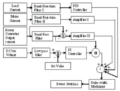
Figure 4. Control Block Diagram of the Hybrid Active Power Filter
The control circuit consists of four feedback signals. First control loop is used to implement the product of the load current and the impedance of the series connected inductor and capacitor. The second loop is used to modify the error of the compensating results of the first loop for improving the compensating performance. And it avoids the uncompensated harmonic components flowing back to the utility. The third one is to generate the virtual harmonic resistor for damping the oscillations that occur between the utility and the active power Filter. The fourth control loop is used for regulating the dc bus voltage.
The first control signal V1 (t) is derived from the equation 1 3.Because equation 3 gives the desired compensation voltage for the harmonic suppression,
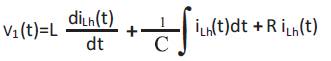
where,
L is inductance of the series connected inductor and capacitor set.
C is the capacitance of the series connected inductor and capacitor set.
R is stray losses of the active Filter and I is the harmonic Lh component of the load current.
The harmonic component present in the load current is extracted using band rejection filter. It is fed to a PID controller to obtain the product of the harmonic components and the impedance of the series connected inductor and capacitor set. The proportional, integral and differential coefficients are the Resistor R, Inductor L, and Capacitor C respectively in the equation 3.
This is based on the theory of conventional hybrid power filter. This control is obtained by extracting the harmonics present in the source current. This is then converted into a voltage (V2 (t)) using the amplifier whose gain (k1) is given by,
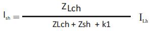
where,
Ish is R.M.S. value of the harmonic component of the source current.
ZLCh is the impedance offered to the harmonic components of the load current by the series connected inductor and capacitor set.
Ilh is the R.M.S. value of the harmonic component of the load current.
The third feedback signal is obtained from the harmonic components of the active power filter current. This is converted into a voltage (V3 (t)) by the amplifier II. The gain (k2) of this amplifier is given by,

where,
Ich(t) is the instantaneous value of harmonic component of the active filter output current.
Due to the switching losses the dc bus voltage cannot be maintained constant. The fourth control loop is used to regulate the dc bus voltage. The voltage regulation of the dc bus voltage is achieved by making the power converter to generate a voltage (v4 (t)) that is in phase or out of phase with the active filter current. For this the product of the fundamental component of the active filter current and the output of the PI controller (k3) is used. This can be described by the following equation.
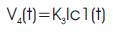
where,
Ic1 (t) is the instantaneous value of the fundamental component of the active power filter current.
The reference voltage Vref (t) of the control circuit is the summation of the outputs of first, second, third and the fourth control loops.
This signal is sent to the pulse-width-modulator so as to produce the drive signals for the power switches of the voltage source converter. The first control signal V1 (t) is the dominant component.
A 25 KV,10 MVA ,50 Hz system supplying a controlled bridge rectifier is considered in this paper. The simulation circuit diagram of the system supplying full bridge controlled rectifier without filter is shown in Figure 5. The simulation is carried out for a period of 100 ms. The source voltage and current waveform for all the three phases are shown in Figures 6 & 7. Figure 7 shows that the source current is not pure sinusoidal. It is a distorted one. The Total Harmonic Distortion (T.H.D) of the source current in each phase is 53%.
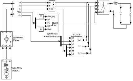
Figure 5. Circuit Diagram of the 25KV,10MVA System Supplying Controlled Rectifier
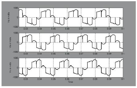
Figure 6. Source Voltage Without Filter
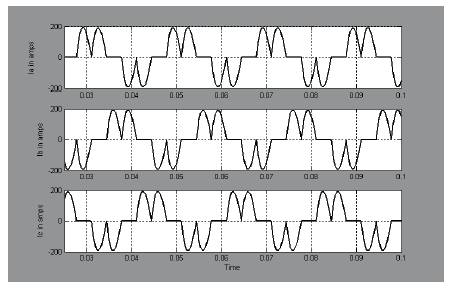
Figure 7. Source Current Without Filter
The simulation circuit diagram of the system supplying full bridge controlled rectifier with filter is shown in Figure 8. The circuit diagram of the filter and its subsystem is shown in Figures 9 & 10. The simulation is carried out for a period of 100 ms. The source voltage and source current waveforms for all the three phases are shown in Figure 11 & 12. Figure 12 shows that the obtained source current is pure sinusoidal. Figure 13 shows the filter current in each phase. It is not a distorted one.
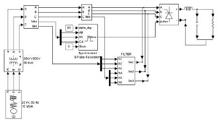
Figure 8. Circuit Diagram of the 25KV,10MVA System Supplying Controlled Rectifier with Hybrid Active Power Filter
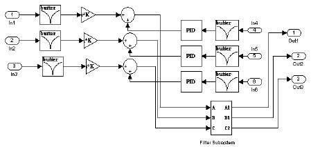
Figure 9. Circuit Diagram of the Proposed Hybrid Active Power Filter
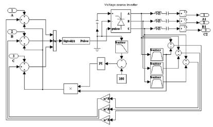
Figure 10. Circuit Diagram of the filter Subsystem
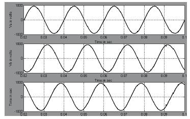
Figure 11. Source Voltage with filter
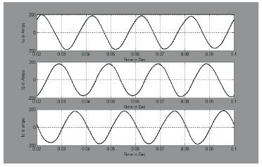
Figure 12. Source Current with filter
The Total Harmonic Distortion (T.H.D) of the source current in each phase is given in Table1. T.H.D in each phase is around 3 % which is within the prescribed limit. It shows that the proposed filter reduces the harmonics in the supply currents.
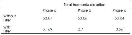
Table 1. Total Harmonic Distortion
In this paper, a novel Hybrid Active Power Filter is proposed. The proposed Hybrid Active Power Filter has the advantages of lower voltage rating for dc capacitor and power switching devices, smaller filter inductor, smaller dimension, lightweight and low Electro Magnetic Interference. The simulation results show that the proposed active power filter is effective and efficient in suppressing the harmonic currents.