Figure 1. Block Diagram
This paper presents simulation and hardware implementation of Load compensation by using DSTATCOM. This proposed DSTATCOM systems includes 1/z controller algorithm for control the system. Contributions are made in several aspects of the whole system, including inverter design, system simulation, controller programming, and experimental setup. The algorithm used for Load compensation by using DSTATCOM is the 1/z controller algorithm. In this method the error current can be measure and compare with reference current to achieve maximum power quality and maximum power deliver to source to load. The DSTATCOM consists of a inverter circuit, which is supposed to operate as the main part of the system, a three phase inverter is used. It provides the opportunity to have either higher or lower output voltage compared with the output. The resultant system is capable of load compensation by using DSTATCOM and obtained high power quality. The 1/z controller algorithm is used to compare error current with reference current and gives gate pulses to the inverter circuit. MATLAB and Simulink were employed for simulation studies. Experimental results indicate the feasibility and improved functionality of the system.
Installation of the diesel engine-based electricity generation unit (DG set) is a widely used practice to feed the power to some crucial equipment in remote areas. DG sets used for these purposes are loaded with unbalanced, reactive and nonlinear loads such as power supplies in some telecommunication equipment and medical equipment. The source impedance of the DG set is quite high, and the unbalanced and distorted currents lead to the unbalanced and distorted threephase voltages at Point of Common Coupling (PCC). Harmonics and unbalanced currents flowing through the generator result in to torque ripples at the generator shaft. All of these factors lead to the increased fuel consumption and reduced life of the DG sets. These forces the DG sets to be operated with derating, which results in to an increased cost of the system. Nowadays, small generator units are available with full con- version (inverterconverter) units to meet stringent power quality norms . Instead of using these, a DSTATCOM can be used with a three-phase DG set to feed unbalanced loads without derating the DG set and to have the same cost involved. For example, a 24-kW lagging power factor load of 0.8 pf will consume 18 kVAR which is 60% of total kVA rating of a 30 kVA generator. The market price of an inverter is $50–70 per kVA which can be easily be configured to work as a DSTATCOM. However, the capital cost of the diesel generator is approximately $500 per kVA rating. Moreover, the DSATCOM can provide compensation for harmonics which facilitates to load the DG set up to its full kVA rating. The performance of DSTATCOM is very much dependent on the method of deriving reference compensating signals. Instantaneous reactive power theory, modified pq theor y, synchronous reference frame theor y, instantaneous id − iq theory, and method for estimation of reference currents by maintaining the voltage of dc link are generally reported in the literature for an estimation of reference currents for the DSTATCOM through the extraction of positive-sequence real fundamental current component from the load current .These techniques are based on complex calculations and generally incorporate a set of low-pass filter which results in a delay in the computation of reference currents and therefore leads to slow dynamic response of the DSTATCOM. In this paper, a fast and simple neural network-based control scheme is used to estimate reference source currents for the control of the DSTATCOM. This paper presents a DSTATCOM for the load compensation of a diesel generator set to enhance its performance. The control of DSTATCOM with capabilities of reactive power, harmonics and unbalanced load compensation is achieved by 1/z controller instead of Least Mean Square (LMS) algorithm based adaptive linear element (Adaline). The 1/z controller is used to extract positive-sequence fundamental frequency real component of the load current. The dc-bus voltage of Voltage Source Converter (VSC) is supported by a Proportional–Integral (PI) controller which computes current component to compensate losses in DSTATCOM. The extraction of reference currents using 1/z controller involves an estimation of weights. These weights are measure of peak of fundamental frequency real current component of the load current. The life of a DG set is enhanced in the absence of unbalanced and harmonic currents. The modeling of the DG set is performed using a synchronous generator, a speed governor, and the excitation control system. This proposed system is simulated under MATLAB environment using Simulink and PSB Block-set toolboxes. The results for a 30-kVA DG set with the linear load at 0.8 lagging pf and a nonlinear load with different load dynamics and unbalance load conditions are presented to demonstrate the effectiveness of DSTATCOM-DG set system.
The main objective is to present a simulation and implement a hardware for achieve maximum load compensation for diesel generator system by using DSTATCOM and 1/z controller.
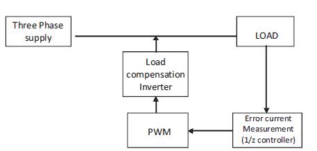
The block diagram for the Load compensation using DSTATCOM is shown in the Figure 1. Here Load compensation technique is used for achieve maximum power delivered from source to load.
DATATCOM – To compensate error current
1/z controller - To provide the gate pulse to the inverter by comparing both reference and error currents.
Three phase supply is given by a Diesel Generator set
PWM – To provide gate pulse to the inverter
According to our program made in 1/z controller, gate signal goes to converter circuit, the gate signals can be achieved by comparing both reference and error currents.
Figure 1. Block Diagram
There is a large number of algorithms that are able to load compensation. Some of them are simple, such as those based on voltage and current feedback, and some are more complicated, such as perturbation and observation. They also vary in complexity, sensor requirement, speed of convergence, cost, range of operation, popularity, ability to detect multiple local maxima, and their applications. Following are the mainly used algorithms in existing systems for load compensation technique.
1.Icosφ Algorithm 2.Fuzzy Logic Controllers
3.Neural Network 4.LMS Algorithm etc.
The algorithm used in this system is 1/z controller which is more superior than the existing ones.
In this project, a fast acting 1/z dc-link voltage controller based on the dc-link capacitor energy is proposed. Conventionally, PI controller is used for this purpose which uses the deviation of the dc-link capacitor voltage from its reference value as input. However, the transient response of the conventional dc-link voltage controllers is slow. In this paper, a fast acting 1/z dc-link voltage controller based on the dc-link capacitor energy is proposed. The detailed modeling and simulation verifications are given to prove the capabilities of this fast acting 1/z dc-link voltage controller over conventional dc-link voltage controller. The results at different operating conditions such as application and removal of loads have been demonstrated to show the capabilities of this controller. The control algorithm is tested under MATLAB Simulink environment under different operating conditions such as switch-on response, application and removal of loads to show the effectiveness of the controller.
The proposed control algorithm for load compensation using shunt active power filter is shown in Figure 3. The instantaneous source voltage of any one phase (phase 'a' in our case Vsa) actual dc-link capacitor voltage Vd, and the instantaneous nonlinear load currents (ULa, iLb, iLC) are the main inputs for the controller. The maximum value of the supply reference current and hysteresis band are sets for initialization of the control process. The controller compares the square values of actual capacitor voltage with reference voltage and the difference i.e. Ver= (Vdcrefj- Vd,2) is added with its previous output. The l/z term is basically serves two purpose, first it delays the controller's output for one sample time and second it introduced an integral term in the control process. The integral operation of controller minimizes the steady-state error in its output. The controller process to update the initial set peak value of supply reference current at every sample by
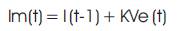
Where Im(t- 1) and Ver(t) are the output of controller and error at (t-1)th and tth sampling instant respectively. The output of the controller is considered as peak value of supply current Im at every samples, which have two components. One of them is the fundamental active component of load current and the other is loss. The unit vector templates for 3-phase system are being generated by instantaneous source voltage of any one the phase (phase 'a' in our case) using Phase-Lock-Loop (PLL). These unit vectors can be expressed as:
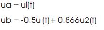
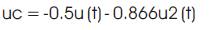
Where, ul(t) = sin cot and u2(t)= cos cot. The peak value Im so obtained is multiplied by the unit sine template (ua, ub, uc) for computing reference source currents (isa*,Isb*,isc* ).The generated reference currents are now compared with instantaneous nonlinear load currents(iLa, iLb, iLc) and the error is processed through hysteresis controller to obtain carrierless pulses to switch the switching devices of the PWM converter. The output equation of hysteresis controller is as:
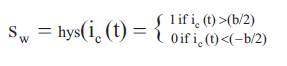
Where, b is the hysteresis band and Sw is the status of the switches, "1" symbolizes ON and "0"symbolizes OFF. The output of hysteresis controller controls the duty cycle of the PWM converter. If i,(t) > b/2 then lower switch is ON otherwise i,(t) < -b/2 then the upper switch is ON. The switching status of each switch in a branch is complementary of one another and hence, when S1= 1, S4= 0 or vice versa. Similar pattern of the pulses are also generated for b and c phases. In practical circuits these pulses are applied to the switches through suitable drivers. By comparing the reference current with error current, the controller provides gate pulse to the inverter. These pulses to the inverter generate an efficient control for DSTATCOM. where it has made a comprehensive comparison between error current and reference current and it shows that the efficiency of experimental results is up to 95%.
Advantages are
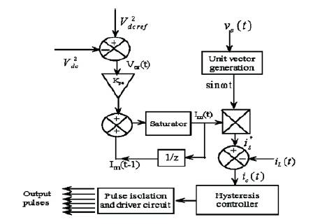
Figure 2. 1/z Controller
When the STATCOM is applied in Distribution system is called DSTACOM (Distribution STACOM) and its configuration is the same, or with small modifications, oriented to a possible future amplification of its possibilities in the distribution network at low and medium voltage, implementing the function so that we can describe as flicker damping, harmonic filtering and hole and short interruption compensation. Distribution STATCOM (DSTATCOM) exhibits high speed control of reactive power to provide voltage stabilization, flicker suppression, and other types of system control. The DSTATCOM utilizes a design consisting of a GTO- or IGBTbased voltage sourced converter connected to the power system via a multi-stage converter transformer. The DSTATCOM protects the utility transmission or distribution system from voltage sags and/or flicker caused by rapidly varying reactive current demand. In utility applications, a DSTATCOM provides leading or lagging reactive power to achieve system stability during transient conditions. The DSTATCOM can also be applied to industrial facilities to compensate for voltage sag and flicker caused by nonlinear dynamic loads, enabling such problem loads to coexist on the same feeder as more sensitive loads. The DSTATCOM instantaneously exchanges reactive power with the distribution system without the use of bulky capacitors or reactors. In most applications, a DSTATCOM can use its significant short-term transient overload capabilities to reduce the size of the compensation system needed to handle transient events. The short-term overload capability is up to 325% for periods of 1 to 3 seconds, which allows applications such as wind farms and utility voltage stabilization to optimize the system's cost and performance. The DSTATCOM controls traditional mechanically switched capacitors to provide optimal compensation on a both a transient and steady state basis.
The three-phase load currents to be compensated (iLa, iLb, and iLc shown in the below Figure 3) are measured from the system and transformed to two phase orthogonal components (ip and iq) on rotating coordinates synchronized with the line voltage. The outputs of the filter circuit are inversely transformed to three-phase components (isa, isb, and isc shown in Figure). The output current of the DSTATCOM is controlled by three-phase current feedback control using isa, isb, and isc as reference signals for each phase. The output signals of the current control added by a sensed system voltage signal becomes the voltage reference signal of the PWM control. The PWM control circuit generates the firing signal of the GTO by comparing triangular wave carrier signals to the voltage reference signal.
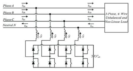
Figure 3. DSTATCOM using three-leg VSC
The authors can see the non sinusoidal, unbalance and distortion produced by the load. We use PSIM software based in Matlab for to obtain, by a time-step simulation, the evolution of different parameters. We can see the non sinusoidal, unbalance and distortion produced by the load. We can see the effect of the DSTATCOM.
The authors have analyzed the operation of a DSTATCOM using three-leg VSC with single dc capacitor. The operation of the switches S1–S6 depends on the control strategy used. Since there is no return path for the zero sequence components of the currents, the three-leg VSC with single dc capacitor cannot inject currents having a zero sequence component.
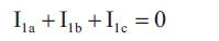
Hence, there will be a zero sequence component in the load current if the load is unbalanced. Full compensation will not be possible as the zero sequence component in the load current cannot be compensated. Hence, the application of this topology is limited (Figure 4).
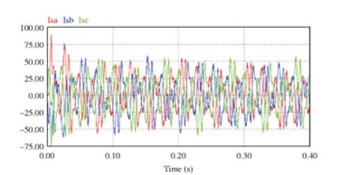
Figure 4. Load currents charts for the three phases.
An H bridge is an electronic circuit that enables a voltage to be applied across a load in either direction (Figure 5). These circuits are often used in robotics and other applications to allow DC motors to run forwards and backwards. H bridges are available as integrated circuits, or can be built from discrete components.
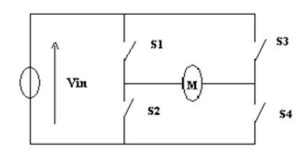
Figure 5. H Bridge.
The two basic states of an H bridge. The H-bridge arrangement is generally used to reverse the polarity of the motor, but can also be used to 'brake' the motor, where the motor comes to a sudden stop, as the motor's terminals are shorted, or to let the motor 'free run' to a stop, as the motor is effectively disconnected from the circuit. The following summaries operation, with S1-S4 corresponding to the Figure 6.
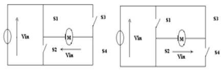
Figure 6. H Bridge operation.
The author are using ATmega8L for producing switching pulses to multilevel inverter. so as to use those vectors which do not generate any common mode voltage at the inverter poles. This eliminates common mode voltage. Also it is used to eliminate capacitor voltage unbalancing. The microcontroller are driven via the driver circuit so as to boost the voltage triggering signal to 9V. To avoid any damage to micro controller due to direct passing of 230V supply to it they provide an isolator in the form of upto coupler in the same driver circuit.
The microcontroller has the following features:
The circuit diagram for the whole system is shown above. Four circuits are combined into a single circuit in the above diagram. It consists of a controller circuit, a driver circuit, a DSTATCOM system and a converter circuit which is the main part of the system. The main AC supply is given to the DSTATCOM system. The DSTATCOM system consists of controller and the Bridge inverter. The converters are selected according to the control pulses from the controller. This boosted supply passes through the source network and the H bridge inverter circuit. By using H bridge inverter we can get output with high power quality (Figure 7).
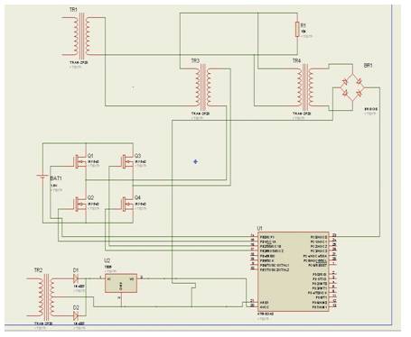
Figure 7.Whole System Circuit Diagram
The MOSFET switch in the converter circuit is controlled by an ATmega8L microcontroller. This ATmega8L microcontroller is driven by a driver circuit. The input to the ATmega8L microcontroller is given through a triggering circuit. The controller will generate pulses which determines the timing sequence of the switch. The pulses produced by the controller will be of 5V.The driver circuit is used to increase this voltage level to be required by inverter.
In this paper, a Diesel generator system employed with DSTATCOM for load compensation, and the necessity of power quality is developed using 1/z controller algorithm. The proposed system was simulated and constructed, and the functionality of the suggested control concept was proven. By connecting a filter in the output side we can get an output without harmonics and efficiency will thus be improved. From the results acquired during the simulations and hardware experiments, it was confirmed that, with a well-designed system including a proper inverter and selecting an efficient and proven algorithm, the implementation of DSTATCOM is simple and can be easily constructed to achieve power quality and load compensation. The results also indicate that the proposed control system is capable of DSTATCOM for maximum power deliver and thus also improves the efficiency power quality and reduces power loss and system cost (Figures 8,9&10).
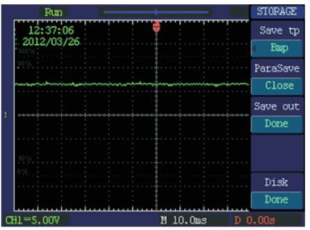
Figure 8. DC output waveform
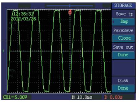
Figure 9. DC Output Waveform
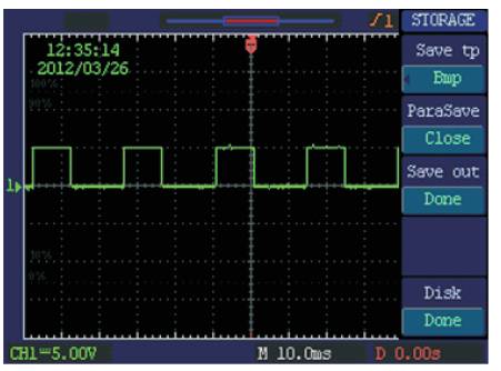
Figure 10. PWM output waveform
In Diesel Generator set there is a huge amount of power loss from source to load. This problem can be overcome by this existing method. Nowadays our economic growth having a major problem with petroleum products. Wastage of diesel in diesel generator set due to power consumption can be recovered by this existing method.