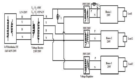
Figure 1. HVDS Block Diagram
This paper presents a new methodology for enhancing the distribution system performance by minimizing both technical and non technical losses. Most of the utility companies in developing countries are victims of major revenue losses due to technical and non technical energy losses. The non technical losses are like electricity theft, unauthorized connections, irregular billing and the technical losses are I2R power losses. These losses affect the quality of supply in terms of voltage magnitude, and more tariffs imposed on genuine customers. To improve the efficiency of supply, one of the recommendations is “Boosting the distributor phase voltage, say from 100% to 152% that is, 230V to 350V and stepping down to normal operating voltage (230V) at the consumer premises by using a special voltage regulator device”. The methodology can reduce the technical and non technical losses in the electrical distribution system up to 36.12% of total power supplied to electrical distribution system. Hence the voltage profile can be improved by reducing the I2R losses. As the normal operating voltage of any home appliances is 230V, in the proposed methodology the electrical distributor phase voltage is maintained up to 350V.So if any domestic consumer tries to get unauthorized/illegal power tapping connection, the home appliances are get damaged due to over voltage. Hence, with this approach there is no chance for power theft or unauthorized connections in the distribution system. When the electrical distributor operates with more voltage than the normal operating voltage, the I2R losses in the distributor will be reduced considerably.
Electrical distribution system that comprises those parts of electrical power system between the sub transmission system and the consumers service. It includes distribution substations, primary distribution feeders, distribution transformers, secondary circuits, including services to the consumer, and appropriate protective and control devices. Electrical distribution networks carry electricity from generation via the Transmission systems to the distribution. In a power system, generation, transmission and distribution of electrical energy involve many losses. They include both technical and non technical losses that occur during generation of electrical energy can be technically defined; whereas the transmission and distribution losses cannot be precisely quantified from sending end information. This proves that the involvement of non technical parameters in transmission and distribution of electrical energy [1]. Technical losses include generation losses (due to turbine efficiency) and losses due to the current flowing in the electrical network such as line losses, copper and iron losses of the transformer. Revenue losses due to Non-Technical losses (also called as commercial losses) associated mainly to the electricity theft that is, un authorized line tapping or meter by passing, non-payment of electricity bills, faulty meters, inaccurate customer electricity billing, and poor revenue collection techniques: The Technical losses occur naturally and are the result of power dissipation in transmission lines.
Transformers and other power system components [9]. Over all the technical losses in Transmission and Distribution system are computed using the information regarding total load and the total energy billed, though the total non-technical losses cannot be precisely computed they can be estimated. Unaccountable losses caused by factors external to the components of the Distribution [6, 11].
One of the major problems in developing countries is electricity theft and it has been very difficult for the utility companies to detect and fight against the people responsible for theft. Electricity theft severely affects genuine customers and utility companies in terms of revenue losses. Utility companies in developing countries struggling economically owing to large amount of pilfered electrical energy during transmission and distribution. In India total Transmission and Distribution losses are as high as 34.54% of total generation, which includes about 20% of unaccounted losses, and there by revenue loss power utility companies was about $ 4.015 billion in the year 2005. Power losses of any distribution system should not exceed 3-5% and in excess of 5% may be attributed to the pilfered energy [2].
Electricity theft includes by-passing the meter, physical methods to evade payment and tampering with the meter. In the past, several techniques were proposed for detection of the location of the theft. On a parallel track some non-technical measures like inspection of the customer premises with suspicious load profiles and campaigning against the theft were implemented to reduce the theft [12]. The non technical losses represent the non-billed energy due to faults or illegal manipulations in the customer's facility. These provoke incoherence's between the registered consumption by the utility company and the real consumption of the customer. This creates severe economical losses for the utility company. The detection of non technical losses uses a lot of techniques of artificial intelligence standing out data mining, statistical techniques and the neural networks as method with more successful in this research field.
In the past several techniques and methodologies were proposed to minimize I2R losses and power theft in electrical distribution systems. To detect electricity theft using support vector machine based data classification, found non-technical losses [1]. To reduce pilfering of electricity using a conceptual design with harmonics [2]. To increasing the efficiency in non technical losses and detection in utility companies using neural networks [3].Determination of energy losses by statistical analysis of loss factor by concentrating constant co-efficient, load curves, load factors [4]. To reduce I2R losses in distribution networks using an application of Ant colony system algorithm and system reconfiguration techniques [5].To minimize electrical energy losses in a local electricity distribution network using a statistical method [6].To minimize power losses in the distribution systems through HVDS concepts [7].Loss minimization in Distribution networks [8].Management of Non-Technical Losses in electrical power networks [9]. Operation of electrical equipment in distribution networks [10]. Energy loss reduction in distribution networks [11].Network reconfiguration for loss reduction using plant growth algorithm [12].Energy loss reduction based on improved reconfiguration method [13]. Minimizing line energy loss of radial distribution feeder with a PV distributed generation unit [14]. Minimum loss network reconfiguration using mixed integer convex programming [15]. Voltage compensation-type inrush current limiter for reducing power transformer inrush current [16]. An ANN based reconfiguration approach for voltage stability improvement of distribution network [17]. This paper proposes a new methodology to minimize the electrical losses (technical and non technical losses) and to improve the voltage profile in the electrical distribution network. The technique deals with voltage boost that is the distributor phase voltage from 230V to 350V by using booster transformer and stepping down the distributor phase voltage at the service mains to normal operating voltage by using a special device, Such that the power theft in the distribution system can be avoided as the normal operating voltage of any home appliances is 230V. Therefore the non technical losses will be minimized and the I2R losses also reduced considerable amount, hence, voltage profile improvement can be achieved.
The biggest challenge in electrical distribution system is to minimize the technical and non technical losses which count around 36.12%. The annual energy losses in the existing distribution system according to APCPDCL are 2747.6 MU. In general the losses in electrical distribution system should not exceed 8% which includes technical and non technical losses [2, 3, 5]. The main problems associated with the electrical distribution system are I2R losses, power theft and the poor voltage profile. Effects of electricity theft are severe and dangerous. Primarily, electricity theft affects the utility company by overloading the generation unit and then its customers. This includes both genuine customers and illegal consumers [1]. The most frequent and dangerous way of pilfering electricity is tapping energy directly from overhead distribution lines (Single phase / three phase). Technical losses include generation losses (due to turbine efficiency), and losses due to the current flowing in the electrical network such as line losses, and copper and iron losses of transformers.
According to Andhra Pradesh Central Power Distribution Company Limited (APCPDCL), India, Town and Municipal Head Quarters energy audit, the energy loss in the distribution system (APDISCOM) due to power theft is as follows.
Power purchase in loss = 14.6%
Loss in major cities like Greater Hyderabad Municipal Corporation, Kurnool, Anantapur is = 592.4 MU that is 12.1%
Loss in other municipal towns is = 7.4%
For all Municipal Head Quarters is = 6.6% and
Percentage of energy loss in Rural area and agriculture loads = 25.4%.
The total power loss in the Distribution System is 266.99 kW when considered to particular area let us say Old City in Hyderabad (South Zone).
The energy loss per year for that particular area is 23, 38, 832 Units.
The prime objective of the proposed methodology is to minimize the energy losses due to technical and non technical (that is 12 R loss and theft).
Certain design issues should be taken into consideration for implementing the proposed methodology. Tapping of electricity from the distributor is often assisted by poor infrastructure of Electrical Distribution System (EDS) [2]. This paper illustrates the electricity theft is impossible for illegal consumers and reducing the power loss in the distribution system. A hardware model is designed in such a way that if any one try for unauthorized connection that is try to tap electricity from any distributor, their home appliances will get damaged. The circuit is designed to make the electricity theft technically impossible to the unlawful customers to tap the electricity from the distributor by the technique of boosting the distributor phase voltage from 230 V to 350 V that is 152 % of the phase voltage using booster transformer. The boosted voltage of distributor continues till the customer's service mains, from there the boosted voltage stepped down to normal operating voltage that is 230V. With this proposed technique, if any illegal customer makes an attempt to tap the electricity from the High Voltage Distributor Line (HVDL), with the increased distributor phase voltage say 350 V, it can prevail the unauthorized connections instead of operating voltage of 230 V. The home appliances which are running through abrupt voltage normally manufactured for an operating voltage of 230 Volts and can withstand till ± 6 Volts of the operating voltage by the policies of Andhra Pradesh electricity regulatory board, with reference to the manufactures if any home appliances running above the rated voltage their life span drastically decreases and later the appliances of the consumer get damaged permanently. By implementing this unique technique in electrical distribution network, to give no option for unauthorized customers to tap the electricity from the distributor knowing their appliances get damaged. The technical losses results in the form of -2 1 R losses will be reduced up to 31.4% and the approximate revenue saving per annum due to lowering only non technical losses that is energy theft is INR. 36, 97,771 (69,370.18 USD) and also the voltage profile can be improved due to reduction in IR drop.
The Figure 1. shows that a 3-phase Distribution Transformer (11 kV/ 415 V/ 230 V), whose secondary is connected to Voltage Booster (230 V / 350 V). A 16 W compact florescent lamp (L1) is connected at secondary side of the voltage booster transformer, across phase (R-Phase) and neutral (N). A special voltage regulator device (SVRD) (350 V/230 V) is placed across the each phase and neutral of the voltage booster, another compact fluorescent Lamp (L2) is connected across secondary side of the SVRD, which is the consumer end.
Figure 1. HVDS Block Diagram
From Figure 1, a Voltage Booster (VB) is used to boost the voltage from 230 V to 350 V, which is called as HVDL. A single phase lamp load L1 is connected across HVDL, due to the abnormal operating voltage (350V), any single phase electrical (home) appliances cannot withstand at this voltage for long time, hence the life of the appliance will get reduced and latter it will get damaged permanently. Based on practical experiment, a 16 W compact florescent lamp (CFL) will made to operate at 350 V (across HVDL), the CFL work for few minutes with high intensity of light and it survives for a maximum period of 6 to 10 minutes and after it will get failed permanently due to high voltage. Then the boosted voltage will be stepped down to normal operating voltage of 230 V by using a special voltage regulator device (SVRD) at the consumer premises and another CFL L2 is connected across the secondary side of SVRD. The Lamp L2 will glow at normal operating voltage for long time. Hence there is no chance for power theft in the distribution system.
The power loss and the voltage drop are reduced to appreciable level and the calculations are done as per the data collected from the APCPDCL, Hyderabad south zone (Old city), India.
There are 12 number of distribution transformers with a line length of 3 km operated to serve an old city area. The resistance/km of a distributor cable is 1.91 Ω. The details of the distribution transformers are: seven numbers of 100 kVA, four numbers of 250 kVA and one 160 kVA distribution transformers.
The total percentage of real power loss is 15.1 %
Energy loss per day is 6407.76 kWh
Energy loss per annum = 23, 38, 832 kWh.
Percentage of Voltage drop (IR drop) is 20 %
Efficiency of the distribution network = 84.89 %
Non-technical losses (Theft) = 5%
The average revenue loss per annum of a particular area (Domestic and Commercial consumers) is INR 1, 16, 94, 162.
Total percentage of power losses is 10.3 %
Total energy loss per day = 4, 381.58 kWh
Energy loss per annum = 15, 99, 278.16 kWh.
Percentage of annual Energy savings = 31.6 %
Revenue saving per annum = INR 36, 97, 771
The percentage of voltage drop = 16.5 %
Efficiency of the distribution network = 89.67 %
The above results are based on experimental analysis; it is observed that there is a great improvement in efficiency of the electrical distribution network by reduction of the real power losses and voltage drop.
After implementing the proposed technique the results in terms of power losses and revenue are obtained and are compared with the existing practical system. Table 1 and Table 2 reveals that the proposed method has 2 succeeded in reducing the I R losses and power theft, voltage drop and improvement in efficiency with great revenue savings. Table 3 shows that the proposed work has been compared with the previous researchers and there is an acceptable improvement in technical and non-technical losses.
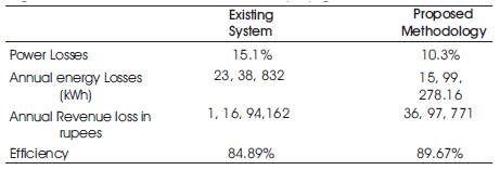
Table 1. Results of proposed method
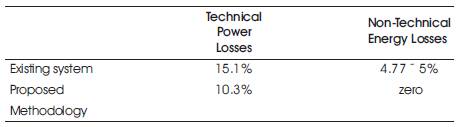
Table 2. Technical and non Technical Losses
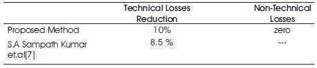
Table 3. Results Validation
The experimental set up of the proposed methodology is shown in Figures 1&2. A lamp load (L1) say Compact Fluorescent Lamp (CFL) of 16W is connected across 350 V (secondary side of step up transformer 350 V / 230 V) and another Lamp with same capacity (L2) is connected across 230V (Secondary side of the step down transformer 350 V/230 V).
Figure 2 it shows that the Lamp (L1) glows to its extreme limit as it is operated at 350 V, where as the Lamp (L2) glows with normal brightness since it is operated at rated voltage that is 230 V.
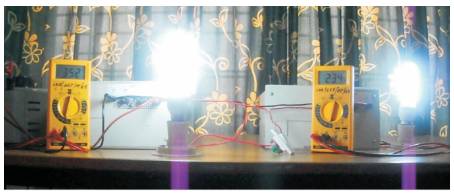
Figure 2. Lamps L1 and L2 are working
Figure 3 shows lamp L1 is failed to operate while lamp L is working. Lamp L failed due to, it made to operate at high voltage (350V) and lamp L survived due to operated at normal voltage (230V).
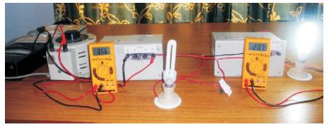
Figure 3. Only lamp L2 is working
This paper discusses method for reducing the non technical losses due to electricity theft and technical 2 losses due to I R losses. The losses in the existing electrical distribution system are very high, every year APCPDCL is losing 2747.6 Million Units of electrical energy. With the proposed methodology there shall be great reduction in -2 I R losses and the revenue saving per annum due to prevention of power theft is rupees 36, 97,771 (69,612.9 USD) and also considerable reduction in the voltage drop upto 4%.
The proposed method requires meager initial expense and at the same time it will assure considerable improvement in the system performance by reduction in technical and non technical losses and also improvement in voltage profile at the far end. The methodology also supports the postponement of power purchase from neighboring states and installation of new power generating plants.
The authors would like to express their profound gratitude to the Principal and the Management of CVR College of Engineering, Hyderabad for their continuous encouragement and support and also authors would like to extend their regards to APCPDCL Hyderabad, for their support by providing relevant data for research work.