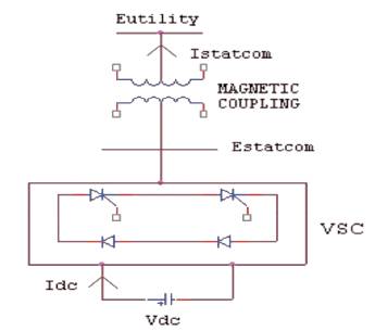
Figure1. Power circuit diagram for STATCOM
This paper deals with the performance of fourteen bus systems with and without STATCOM using five level inverter VSI circuit. The VSI is extremely fast in response to reactive power change. A Static Compensator (STATCOM) is a device that can provide reactive support to a bus. It consists of voltage source inverters connected to an energy storage device on one side and to the power system on the other. STATCOM is a device which can supply the required reactive power at low values of bus voltage and can also absorb active power if it has large energy storage. It also required having less harmonic contents in the output and higher compensation VA capacity. When the reactive power of the load is changing continuously, a suitable fast response compensator is needed. STATCOM, TCTC, UPFC, TCSC, SVC are the compensators belonging to FACTS devices. Models for the STATCOM is developed using MATLAB simulink. The simulation of the STATCOM is performed in the Simulink environment and the results are presented.
In Electrical Power distribution networks, it is essential to balance the supply and demand of active and reactive power in an electric power system. If the balance is lost, the system frequency and voltage excursion may occur resulting, in the worst case, in the collapse of the power system. Appropriate voltage and reactive power control is one of the most important factors for stable power system. The distribution system losses and various power quality problems are increasing due to reactive power.
FACTS, which are power electronic based devices can change parameters like impedance, voltage and phase angle. Therefore they have the ability to control power flow pattern and enhance the usable capacity of the existing lines. The important feature of FACTS is that they can vary the parameters rapidly and continuously, which will allow a desirable control of the system operation[7].
FACTS devices are good to improve the power system efficiency, improve power factor and reduced in harmonics. Reactive power is used to control the voltage levels on the transmission system to improve the efficiency of the system. The main application of power electronics in new configuration known as Flexible AC Transmission Systems (FACTS) offers the possibility of meeting such demands. In order to increase the power transfer capability normally FACTS devices are employed[1].
Among all the FACTS devices, The STATCOM has the higher potential[7] to be exceptionally reliable with the added capacity to sustain reactive current at low, reduce land use and increased relocatability and be developed as a voltage and frequency support[1-3].
This paper deals with the effect STATCOM in a fourteen bus system and how well it has improve the system performance on the basis of voltage and reactive power control. A static compensator is an important member of the family of controllers known as Flexible AC Transmission System (FACTS). An ideal STATCOM can be considered as a three phase sinusoidal voltage source that can control its magnitude as well as its phase displacement. The STATCOM is basically a DC-AC voltage source converter with an energy storage unit, usually a DC capacitor. It operates as a controlled. Synchronous Voltage Source (SVS) connected to the line through a coupling transformer [4, 5, 7].
The above literature does not deal with the use of five level inverter for STATCOM. The work proposes five level inverter for the control of reactive power.
One of the many devices under the FACTS family, a STATCOM is a regulating device which can be used to regulate the flow of reactive power in the system independent of other system parameters. STATCOM has no long term energy support on the dc side and it cannot exchange real power with the ac system.
In the transmission systems, STATCOM is primarily handle only fundamental reactive power exchange and provide voltage support to buses by modulating bus voltages during dynamic disturbances in order to provide better transient characteristics, improve the transient stability margins and to damp out the system oscillations due to these disturbances.
STATCOM is a shunt connected reactive power compensation device. It is capable of generating & absorbing the reactive power. It can be improve the power system in the areas are:
The power circuit diagram for STATCOM as shown in Figure 1. It is a controlled reactive power source. It provides the reactive power generation and absorption by means of electronic process of the voltage and current waveforms in a voltage source[10]
STATCOM controller provides voltage support by generating or absorbing reactive power at the point of common coupling without the need of large external reactors or capacitor banks[11]. It is a compact design, small foot print, low noise and low magnetic impact. The exchange of reactive power between the converter and AC system can be controlled by varying the three phase output voltage, Es of the converter.
A single line diagram of STATCOM is shown in Figure 2, where VSC is connected to the utility bus through the magnetic coupling transformer. It is a compact design, small foot print, low noise and low magnetic impact. The exchange of reactive power between the converter and AC system can be controlled by varying the three phase output voltage, Es of the converter.
If the amplitude of the output voltage is decreased below the utility bus voltage, then the current flows through the reactance from the ac system to the converter and the converter act as inductance and it absorbs the reactive power for the ac system.
If the output voltage equals the ac system, then the reactive power exchange becomes zero. On that condition STATCOM is to be in a floating state.
STATCOM controller provides voltage support by generating or absorbing reactive power at the point of common coupling without the need of large external reactors or capacitor banks.
Figure1. Power circuit diagram for STATCOM
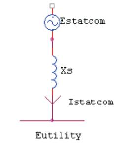
Figure 2. Line diagram of STATCOM
Five level output is obtained by cascading two inverters. Multilevel output is obtained by adding pulses of the two inverters. The output has reduced harmonics. Therefore five level inverter can give output of better quality.
The simulation is done by using mat lab simulink [9] and the results are presented. Each line is modeled by its series impedance. The load is represented by the combination of R and L. The shunt capacitances of the line are neglected. Circuit model of thirty bus system without controller is shown in Figure 3. The voltage waveform across Load 1 and Load 2 without controller are shown in Figure 4. The Real and Reactive power at Load without controller are shown in Figure 5.
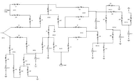
Figure 3. 14 bus system without STATCOM
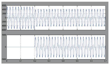
Figure 4. Voltage waveforms across Load 1 and Load 2
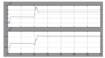
Figure 5. Real and Reactive power at Load
The circuit with STATCOM is shown in Figure 6. In the thirty bus system, the STATCOM is installed in bus 3. The matlab simulink [9] diagram for VSI fed STATCOM model is shown in the Figure 7.The output voltage for five level STATCOM is shown in the Figure 8. The Voltage waveform across the load 1 and load 2 with controller is shown in Figure 9. The Real and Reactive power at load with controller are shown in Figure 10. The summary of Real and Reactive power for normal system and VSI STATCOM system is given in Table 1. The summary of Real and Reactive powers with and without controller for fourteen bus system is given in Table 2. It can be seen that the reactive power is increased at bus 3 due to the presence of STATCOM. The increase in the Reactive power is due to the increased voltage of that bus. The summary of voltages with and without controller for fourteen bus system is given in Table 3. From the Table 3 it is seen that the voltage is increased at bus 3 due to the presence of STATCOM.
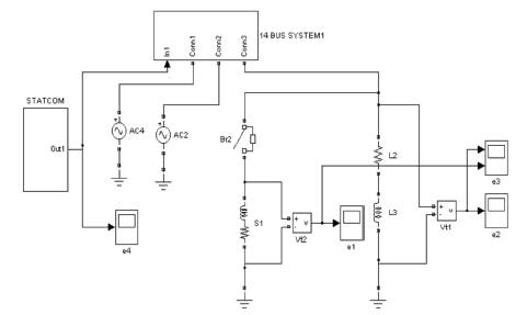
Figure 6. 14 bus system with STATCOM
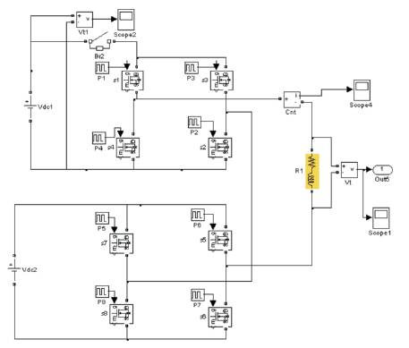
Figure 7. VSI Fed STATCOM Model
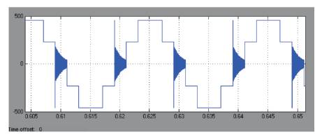
Figure 8. Output Voltage for five level STATCOM
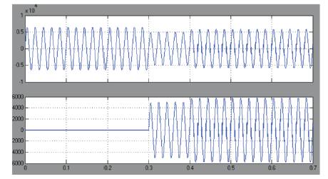
Figure 9. Voltage waveforms across Load 1 and Load 2
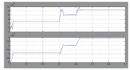
Figure 10. Real and Reactive power at Load
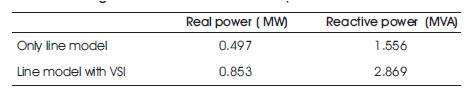
Table 1. Summary of Real and Reactive power for normal and VSI STATCOM system
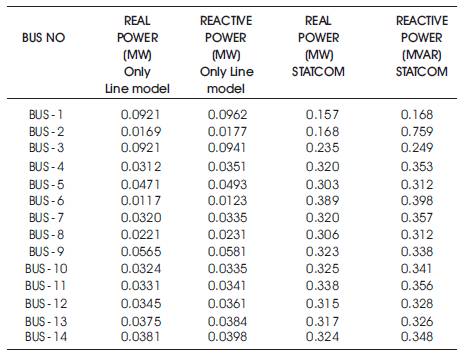
Table 2. Summary of Real and Reactive power for fourteen bus system with and without controller
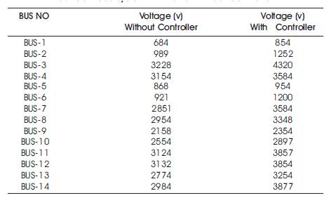
Table 3. Summary Of Voltages For Different Buses
Power system with STATCOM are analyzed and the circuit model for the system is developed using the blocks available in MATLAB. Fourteen bus system with and without STATCOM are simulated and the results are presented. The sag is reduced by using STATCOM.This system has reduced reliability and improved power quality. The simulation results are in line with the predictions. Voltages and Reactive power increase when the STATCOM is connected to the respective buses. The scope of the present work is the digital simulation of systems with STATCOM using mat lab. The hardware implementation yet to be done.