(1)
Voltage-source inverters with space vector PWM strategy are gaining importance in high power high performance industrial applications. This paper presents open loop V/HZ control of induction motor drive based space vector pulse width modulation (SVPWM) technique. The proposed system has been implemented using DSP (TMS320F2812) controller and demonstrated through hardware and simulation results. From the results it shows that this system makes a good performance on motor control.
In commercial and industrial applications, motor controllers are increasing because of their improved efficiency, energy savings. Lower speed range and a high computational effort are the drawbacks of these controllers. At low speeds the more complex they are the better are their performance. DSP based controllers are becoming a standard product with increasing their performance.
DSP offer an easy way to regulate both the frequency and voltage applied to a motor. As a result much higher efficiency can be achieved by these motor drives. In this paper the experimental test has been developed around DSP320F2812 processor. The DSP (TMS320F2812) controller is used to read the current speed of motor then give the fit able PWM generation to the motor. This method, do not need to look into induction motor's parameters which makes it inexpensive for implementation.
Many new industrial applications that require superior performance, employing Pulse Width Modulation variable speed drives. Three phase inverters generally employ sine triangle PWM (SPWM) technique because of its simplicity and SVPWM technique. The SVPWM technique gives a good D.C utilization and flexibility in switching state selection. The best feature of this technique is that this method is simple to implement on digital controllers and has reduced computational efforts. The proposed work is to develop a simple SVPWM technique and its implementation on TMS320F2812 fixed point DSP controller.
In SVPWM method, the voltage reference is provided using a revolving reference vector. SVPWM utilizes dc bus voltage efficiently and generates less THD in a three phase voltage source inverter.
The proposed work focuses on step by step development SVPWM implemented on an Induction motor. The model of a three-phase a voltage source inverter is discussed based on space vector theory. The Pulse Width Modulation (PWM) Technique called “Vector Modulation”, which is based on space vector theory, is the most important development in the last few years.[ .Vinoth Kumar & K.Kishore Reddy &S.Suresh Kumar, 2010, p.4585-4594K; Ying-yu Tzou & Hau-Jean Hsu & Tien-Sung Kuo, 1996 p.138-143; Wenxi Yao &Haibung Hu,& Zhengyu Lu, 2008,p. 45 – 51].
Although, several PWM methods have been created in the past, the vector modulation technique appears to be the alternative for a three phase switching power converter [ J. Klima, 2002, p. 1334 – 1339; G. Narayanan & V.T. Ranganathan, 2002,p.788 -789; Bosquets Monge. & S, Bordonau. J & Rocabert. J, 2008, p.1964 -1972.].
The circuit for a three-phase voltage source PWM inverter is shown in Figure 4. S1 to S6 are the six power switches that shape the output, which are controlled by the Switching variables a, a′, b, b′, c and c′. When an upper transistor is switched on, i.e., when a, b or c is 1, the corresponding lower transistor is switched off, i.e., the corresponding a′, b′ or c′ is 0. Therefore, the on and off states of the upper transistors S1, S3 and S5 can be used to determine the output voltage.
The SVPWM method considers this interaction of the three phases.
These are applied to the three phase induction motor, using (4). A three phase inverter, From Figure 1, has 8 permissible switching states. Table 1 gives summary of the switching states and the corresponding phase-to-neutral voltage of isolated neutral machine.
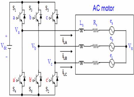
Figure 1. Three-phase Voltage Source PWM Inverter.
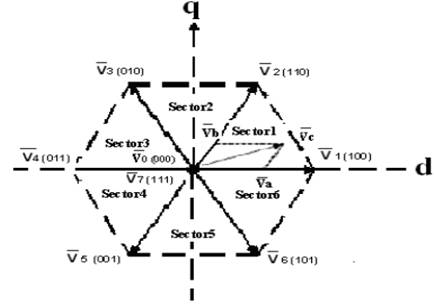
Figure 2.Space Vector of Voltage
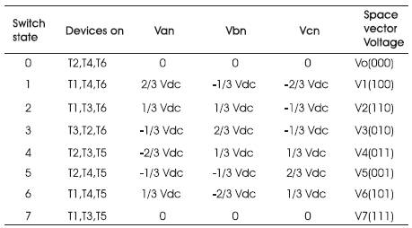
Table 1. Inverter Switching States
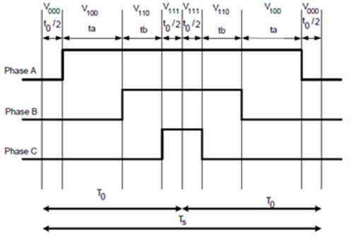
Figure 3. Pulses in sector-1
Space Vector PWM (SVPWM) refers to a special switching sequence of the upper three power transistors of a three-phase power inverter.
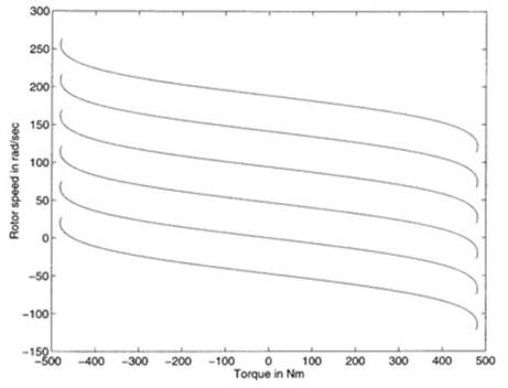
Figure 4.Torque Speed Curves with Constant air Gap flux
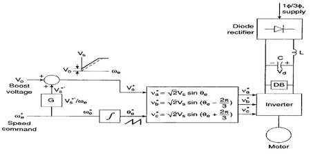
Figure 5. Block Diagram of Open Loop V/HZ Control
Scalar Control (V/HZ Control) is one common speed control technique for variable frequency drives (VFDs, frequency changers, frequency inverters) in the industry. In this type of control, the motor is fed with variable frequency signals generated by the Pulse Width Modulation (PWM) control from an inverter. Here, the V/HZ ratio is maintained constant in order to get constant torque over the entire operating range. As the name “Scalar control”, only magnitudes of the control variables (frequency and voltage) are controlled. Generally, the drives with such a control are without any feedback devices (open-loop control). Hence, a control of this type offers low cost and is an easy-to-implement solution.
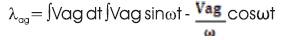
Generally, an induction motor requires nearly constant amplitude of air gap flux for satisfactory working of the motor. Since the air gap flux is the integral of the voltage impressed across the magnetizing inductance, and assuming that the air gap voltage is sinusoidal, λag is given as (5),
The torque-speed curves with a constant air gap flux shown below:
Since the stator flux is maintained constant, independent of the change in supply frequency, the torque developed depends on the slip speed only. So by regulating the slip speed, the torque and speed of an AC Induction motor can be controlled with the constant V/Hz principle.
As seen from the Figure 7 the voltage and the frequency are varied at constant ratio up to the base speed. Beyond the base speed, the supply voltage cannot be increased. Increasing the frequency beyond the base speed results in field weakening and the torque reduces. At frequencies higher than the rated value, the constant V/Hz principle also have to be violated because, to avoid insulation break down, the stator voltage must not exceed its rated value.
The basic block diagram of open loop V/HZ control implementation can be shown in Figure 6.
Figure.4 illustrates the operations sequence of the C code of the V/Hz control that xcud CCStudio 3.1 platform. As shown in Figure 7 the Controller sample times are governed by the DSP timer called a CpuTimer0, which generates periodic interrupt at each sampling time Ts [ G. Narayanan & V.T. Ranganathan, 2002,p Bosquets Monge. & S, Bordonau. J & Rocabert. J.]
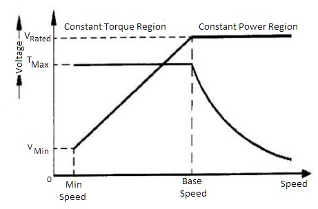
Figure 6. V/HZ Curve
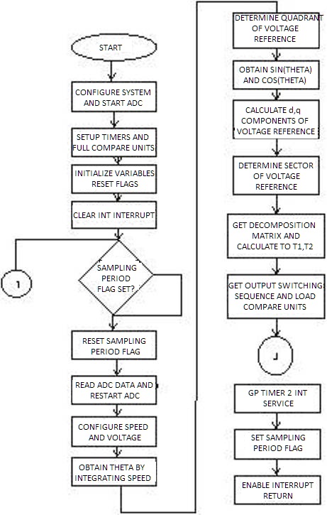
Figure 7. Flow chart of Controller Main Algorithm Implemented in DSP
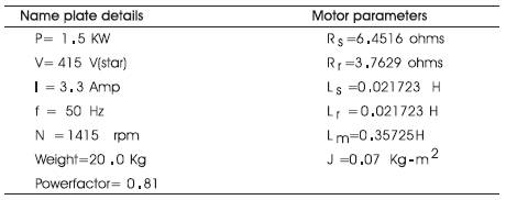
Table 2. Parameters of the Induction Motor
The major features of this implementation are 32-bit integration to obtain the phase of the reference voltage vector, to calculate sin and cos functions, sector-based table look-up for decomposition matrix and sector-based table look-up for PWM channel.
GP Timer 1 is used as the time base for PWM generation with the Compare Units. GP Timer 2 is used to time the sampling period allowing independent control of sampling frequency from PWM frequency. An ADC channel is used to input the speed command. It is assumed that the accuracy of speed response is not a concern therefore open-loop speed control is implemented. Applications such as blower/fan drives typically don't care too much about the accuracy in speed response.
The major steps involved in this implementation are: q Integrate the command speed to get the phase, theta, of the reference vector; q Determine the quarter theta is in, map theta to the first quarter and record the correct signs of SIN(θ ) and COS(θ ); q Use θ based look-up table to obtain SIN(θ ) and COS(θ ) and the d and q components of the reference voltage vector; q Determine the sector, s , θ is in; q Use s based look-up table to find the decomposition matrix and decompose the reference voltage vector; q Use based look-up table to determine which PWM channel toggles first, second and third and load the compare registers with appropriate values [ A.Isidori, 1989].
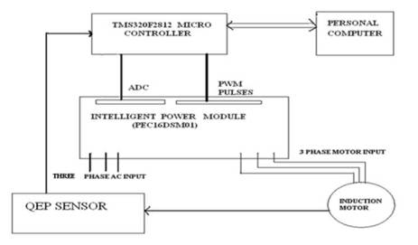
Figure 8. Block diagram of 3-phase Induction Motor Controller
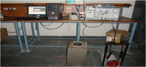
Figure 9. Experimental Set up
The experimental tests were performed with a 1.5kW induction motor, controlled by DSP320F2812. The switching frequency of the PWM inverter was control by DSP controller. The adopted technique to drive the induction motor is to perform all the computational tasks inside the interrupts generated by the PWM core of the processor.
The induction motor's parameters are presented by Table 2. The overall block diagram of 3-ph induction motor controller implementation can be shown in Figure 8.
The hardware components used in this experiment consist of DSP TMS320F2812 dedicated motor controller that is equipped with analog inputs, encoder inputs and PWM output channels. The PWM output channel is fed to a gate drive and then to the IGBT inverter. The IGBT inverter module directly linked to the induction motor. The analog inputs of the DSP are used to read the stator flux. The software components consist of DSP programming tools and motor control development environment that can be used as Human Machine Interface (HMI). Estimation and control signal computation are implemented using C Language in the Development Tool Environment. The program is compiled on DSP compiler software and then the resulted object is downloaded to the DSP board using HMI subsystem.
The Simulated results are shown in Figure10, Figure.11, and Figure12. The Experimental results are shown in Figure13, Figure14.
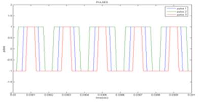
Figure10. SVPWM Pulses
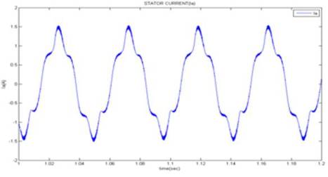
Figure 11. Winding Current
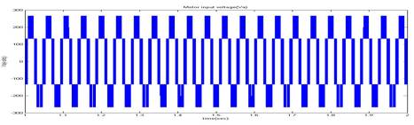
Figure 12 Inverter Output Voltage
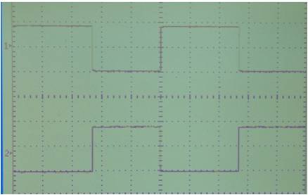
Figure 13 SVPWM pulses Magnitude of the pulse =1*1= 1V Time period = 1*20 msec = 0.02sec
Magnitude of the current (Ia) =2.8 *1= 2.8A
Time period = 2.2*20 msec = 0.04sec
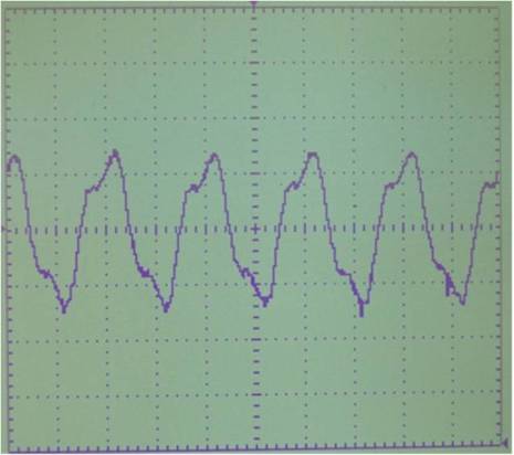
Figure 14. Winding Current Magnitude of the current (Ia) =2.8 *1= 2.8A Time period = 2.2*20 msec = 0.04sec
DSP based open loop V/HZ control of three phase induction motor drive is implemented. Based on the experimental results, it can be concluded that.
The SVPWM based voltage/frequency controller of induction motor can give better transient and steady state performance.