(1)
The problem of low power factor, power loss, heating of the machine and telephonic interference necessitates techniques to eliminate harmonics. The main objective of harmonic elimination is to produce the fundamental while not generating specifically chosen harmonics. The output voltage waveform of an inverter is given by Fourier series expansion which contains both the fundamental and the harmonics. Suitable technique has to be used to solve the transcendental equation. Traditional optimization methods suffer from various drawbacks, such as prolonged and tedious computational steps and convergence to local optima, thus, the more the number of harmonics to be eliminated, the larger the computational complexity and time. So in this research work, Pattern Search (PS) method has been employed to eliminate the harmonics. Using pattern search technique, the transcendental equations are solved and switching times (angles) that produce only the fundamental without generating any specific harmonic order is found. This is referred to as harmonic elimination or programmed harmonic elimination as the switching angles are chosen (programmed) to eliminate specific harmonics.
The problem of eliminating harmonics in switching converters has been the focus of research for many years. If the switching losses in an inverter are not a concern (i.e. switching on the order of a few kHz is acceptable), then the sine-triangle PWM method and its variants are very effective for controlling the inverter [1]. This is because the generated harmonics are beyond the bandwidth of the system being actuated and therefore these harmonics do not dissipate power. On the other hand, for systems where high switching efficiency is of utmost importance [15], it is desirable to keep the switching frequency much lower [5].
In this case, another approach is to choose the switching times (angles) in such a way that a desired fundamental output is generated and specifically chosen harmonics of the fundamental are suppressed [1-5]. This is referred to as harmonic elimination or programmed harmonic elimination as the switching angles are chosen (programmed) to eliminate specific harmonics. Specifically, in [2-4], the harmonic elimination problem was formulated as a set of transcendental equations that must be solved to determine the switching times (angles) in an electrical cycle for turning the switches on and off in a full bridge inverter so as to produce the fundamental while not generating specific harmonic order, for example, the third and fifth harmonics. These transcendental equations are then solved using techniques such as iterative numerical techniques [1], Selective harmonic elimination [6], Programmed PWM technique [7], elimination using resultants [10, 16], Genetic Algorithm [9], etc., to compute the switching angles. However, the drawback of these methods is heavy computation burden and complicated hardware [8]. The main challenge of solving the associated nonlinear equation, which are transcendental in nature and therefore have multiple solutions, is the convergence. It is generally accepted that the performance of an inverter, with any switching strategy, can be related to the harmonic contents of its output voltage [17]. Here a method is presented to solve the transcendental equations whose solutions are highly reliable with fast converging characteristics.
Direct Search (DS) methods are evolutionary algorithms used to solve constrained optimization problems. DS method does not require any information about the gradient of the objective function at hand, while searching for an optimum solution. This family includes PS algorithms, Simplex Methods (SM) (different from the simplex method used in linear programming), Powell Optimization (PO) and others. The PS method is a technique that is suitable to solve a variety of optimization problems that lie outside the scope of the standard optimization methods. Generally, PS has the advantage of being very simple in concept, easy to implement and computationally efficient. Hence it can be used to solve the transcendental equations involving harmonics.
In this section, the mathematical formulation of the problem is presented for both the unipolar and bipolar cases.
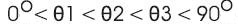
Figure. 1 shows the standard bipolar PWM waveform [13] with 3 switching angles θ1, θ2 and θ3.
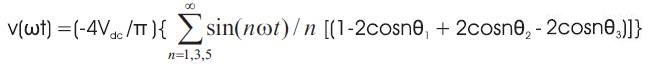
Fourier series expansion of inverter output voltage is given by, .


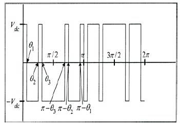
Figure 1. Bipolar PWM Waveform
The Fourier series expansion of unipolar waveform [13] is given by :

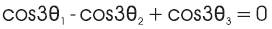
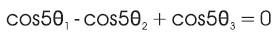
The problem is to find the unknown angles with transcendental equations as follows:

This formulated problem will be solved using PS method whose objective function aims to minimize the harmonic equations subject to the constraints [11-13],
The PS optimization routine is a derivative free evolutionary technique that is suitable to solve a variety of optimization problems that lie outside the scope of the standard optimization methods. Generally, PS has the advantage of being very simple in concept, and easy to implement and computationally efficient algorithm [11]. Unlike other heuristic algorithms, such as GA, PS possesses a flexible and well-balanced operator to enhance and adapt the global and fine tune local search.
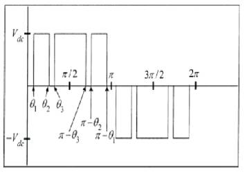
Figure 2. Unipolar PWM Waveform
The PS algorithm proceeds by computing a sequence of points that may or may not approach the optimal point. The algorithm starts by establishing a set of points called mesh, around the given point. This current point could be the initial starting point supplied by the user or it could be computed from the previous step of the algorithm. The mesh is formed by adding the current point to a scalar multiple of a set of vectors called a pattern. If a point in the mesh is found to improve the objective function at the current point, the new point becomes the current point at the next iteration.
This may be better explained by the following:
First Step: The Pattern search begins at the initial point X0 that is given as a starting point by the user. At the first iteration, with a scalar of magnitude 1 called mesh size, the pattern vectors are constructed as [0 1], [1 0], [−1 0],and [0 −1], they may be called direction vectors. Then the PS algorithm adds the direction vectors to the initial point X 0 to compute the following mesh points:
X 0 + [1 0]
X 0 + [0 1]
X 0 + [−1 0]
X 0 + [0 −1]
Figure 3 illustrates the formation of the mesh and pattern vectors. The algorithm computes the objective function at the mesh points in the order shown.
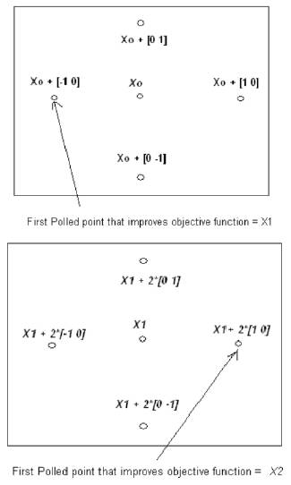
Figure 3. PS Mesh points and Pattern
The algorithm polls the mesh points by computing their objective function values until it finds one whose value is smaller than the objective function value of X0. If there is such point, then the poll is successful and the algorithm sets this point equal to X1, (X 0 + [−1 0] as in Figure 3).
After a successful poll, the algorithm steps to iteration 2 and multiplies the current mesh size by 2, (this is called the expansion factor and has a default value of 2). The mesh at iteration 2 contains the following points: X1+ 2*[1 0], X1+ 2*[0 1], X1+2*[-1 0] and X1+ 2*[0 -1]. The algorithm polls the mesh points until it finds one whose value is smaller than the objective function value of X 1. The first such point it finds is called X 2, (X1 + 2*[1 0] as in Figure. 3.), and the poll is successful. As the poll is successful, the algorithm multiplies the current mesh size by 2 to get a mesh size of 4 at the third iteration.
Second Step: Now if in iteration 3, none of the mesh points has a smaller objective function value than the value at X2, the poll is called an unsuccessful poll. In this case, the algorithm does not change the current point at the next iteration, i.e., X3= X2. At the next iteration, the algorithm multiplies the current mesh size by 0.5, a contraction factor, so that the mesh size at the next iteration is smaller. The algorithm then polls with a smaller mesh size. The PS optimization algorithm will repeat the illustrated steps until it finds the optimal solution for the minimization of the objective function. The PS algorithm stops when any of the following conditions occurs:
All the parameters involved in the PS optimization algorithm can be pre-defined subject to the nature of the problem being solved.
Figure 4. Best function value Vs iteration for m= 0.6
To obtain the best and optimum solution for the given non-linear transcendental equations, the following PS parameters were used.
Mesh tolerance: 1e-006
Maximum iterations: 100 * no. of variables
Maximum function evaluations: 2000 * no. of variables.
Using the proposed PS technique the equations of unipolar case is solved and the three switching angles were found for m = 0.6. The plots obtained using pattern search tool is given below.
This process is repeated for various modulation indices from 0.1 to 1.3 for both unipolar and bipolar cases.
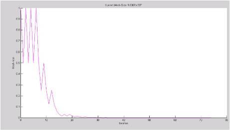
Figure 5. Current mesh size Vs iteration for m= 0.6
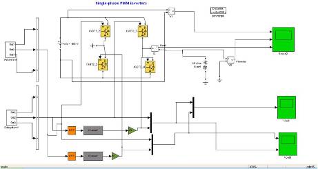
Figure 6. Simulation Diagram for Elimination of Selected Harmonics
Let us consider the following example, inverter circuit to produce unipolar output pattern. It is connected with an RL Load as shown below. Simulations were carried out on a Intel Core 2 Duo 1.8GHz, 512 MB RAM processor. The rating of the proposed AC drive system was
DC power supply : 100 V
Load resistance : 10 ohms
Load inductance : 5 mH
Modulation index : 0.6
The switching pattern required to eliminate the 3rd and 5th harmonics in an single phase inverter's output waveform is given in Figure 7.
Figure 8 shows the output voltage and current waveforms obtained after the application of switching angles calculated using Pattern Search method.
Figure 9 shows the various harmonic levels present in the output voltage waveform. Elimination of 3rd and 5th harmonics reduces THD to 70.51%. Further the THD value can be reduced by eliminating more number of harmonic orders. This, will in turn increases the number of estimated switching angles.
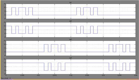
Figure 7. Unipolar Switching
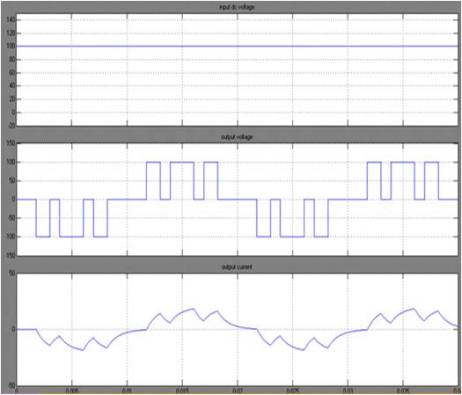
Figure 8. Unipolar output voltage and current waveforms
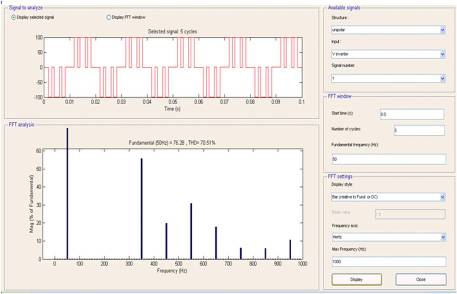
Figure 9. FFT after Implementation of obtained Solution
Table 1 shows the firing angles obtained to eliminate the 3rd and 5th harmonics present in the inverter output for different modulation indices. The corresponding percentage voltage total harmonic distortion (THD) is also given. As the lower order harmonics are eliminated by selective harmonic elimination, only higher order harmonics will be present in the output. Designing a suitable low pass filter will further reduce the %THD to a minimum value.
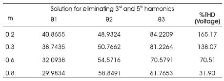
Table 1. PS based computed switching angles to eliminate 3 and 5 harmonics for different values of m
The research work has successfully implemented selective harmonic elimination. The similar work using Pattern Search methodology can be carried out for further cases and best results can be obtained. The paper has described the simulation results of unipolar case. Thus Selective Harmonic Reduction Method is always superior when compared to all other Harmonic Reduction Techniques. Further work should focus on real time implementation of SHE-PWM inverters.