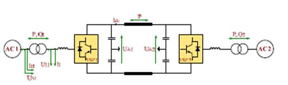
Figure 1. Basic Schematic Concept of VSC-HVDC Transmission System
The stability of power systems is of paramount importance in order to maintain the integrity of power supply to the grid, recently, due to advancement of power electronics Technology, High Voltage Direct Current (HVDC) transmission technology and Voltage Source Converter (VSC) has been utilized to enhance power system stability. The HVDC is very reliable, flexible and cost effective. The capability of rapidly control both active and reactive power independent of each other allows VSC-HVDC to enhance transient stability, increase damping of electromechanical oscillations and improve voltage stability. Voltage collapse usually occurs following a large disturbance in heavily stressed power systems, which results in increased reactive power and hence leads to a voltage drop. Restrictions in the power system to provide reactive power together with the control of mechanism that try to restore the voltage magnitude at operating conditions often lead to voltage instability. Fuzzy logic based intelligent control has been used in order to optimize efficiency and enhance performance. Fuzzy logic control does not require precise mathematical modeling of the system nor complex computations. This control technique relies on the human ability to understand the system behavior and is based on qualitative control rules. In this paper a new control strategy of VSC HVDC has been developed. The controller is of function based fuzzy controller and describes the advantages of function based fuzzy controller over conventional PI controller. The model was analyzed for three phase fault at different locations. The fuzzy-logic-based control of the system helps to optimize the efficiency of the link under these disturbances.
The HVDC technology which based on thyristor valve has been developed since 1970s. Mainly due to cost consideration, the HVDC with thyristor valve is mostly used for large point-to-point transmissions, often over long distances across land or under water. However, it exits commutation failure problem, thyristors cannot be off immediately, and it also requires 40-60% reactive power supply of active power transmitted. To overcome the above shortcomings, IGBT switches will be utilized in this study. The advantages of IGBT over thyristor include [1, 2] (i) IGBT can switch off and on immediately, (ii) there is no commutation failure problem, (iii) no telecommunication required between two stations of VSC (Voltage Source Converter)-based HVDC system, (iv) active and reactive power controlled independently,(v)reactive power compensation not required, (vi) only small filter is required to filter high frequency signal (vii) no restriction on multiple in-feeds, and etc. VOLTAGE Source Converter (VSC) based High Voltage Direct Current (HVDC) schemes using insulated-gated bipolar transistors (IGBTs) (known as VSC-HVDC) have attracted increasing attention [3-9]. The main advantages of VSC-HVDC as schematically shown in Figure1, when compared to conventional HVDC systems based on line commutated thyristor converters, include:
i) No requirement for external voltage source for commutation. ii) Ability to control the reactive power flow independently at each end and independently of the active power control.
Till date thyristor based converters are widely used for HVDC transmission system. Since for a long period it is working, so many researchers have been done for its control and this system is now well established. Though this system is working very successfully it has certain remarkable limitations. As a result VSC based HVDC light system using
IGBT technology has attracted the attention of many researchers in this field [10]. Here the control strategy discussed is slightly different from the conventional PI controller. A new control strategy of VSC HVDC has been developed using fuzzy controller [11]. This paper describes the advantages of function based fuzzy controller over conventional PI controller. The validity of all the controllers and filters have been tested by computer based simulation using MATLAB/ SIMULINK.
VSC-HVDC has many advantages compared with the traditional HVDC. One advantage is possible support of weak AC systems or even passive systems without phase-change Voltage. Focusing on this, some mathematic models and control structures of the VSC-HVDC have been proposed Parameter optimization for the controller has not been taken into account so that conventional PI control cannot meet the challenge of the practical system at different operating modes. Focusing on these deficiencies, this paper uses fuzzy PI control algorithm. Many theories, studies, experiments have proven that fuzzy PI controller has good control performance [12]-[ 14]. The fuzzy PI parameter self-adapting module combined with the PI control is designed to weaken the influence of system fluctuations on control effectiveness. The PI parameter will be self-adjusting in response to different running conditions when the system is running. At the meantime, the concept of the functioning-fuzzy-subset inference is introduced into this module to simplify operation. [15]
Figure 1. Basic Schematic Concept of VSC-HVDC Transmission System
In HVDC transmission, the conversion of AC to DC occurs at the Transmitting end (rectifier) and the inversion of DC to AC occurs at the receiving end (inverter). Converters consist of high voltage Bridges and tap changing transformers, the valve bridges consist of High voltage valves connected in 6-pulse or 12-pulse arrangement. One of the advantages of this technology is the fault-blocking Characteristics of the system which enables it to serve as an automatic Firewall for blackout prevention in case of cascading events, which is Impossible with flexible alternating current transmission system (FACTS) [16].
In this study the hybrid HVDC-HVAC solution was investigated and the HVDC link used was the mono-polar link system as shown in Figure 2. Power flow equations of HVDC line is given as follows
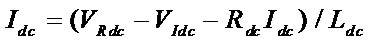
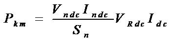
B is number of bridges in series and Q is the power factor angle Vdor, Vdoi are the voltages at rectifier and inverter respectively, Zc and Xc are the characteristic impedance and commutating reactance respectively. And Rcr, Rci and RL are the resistance at rectifier, inverter and the DC line respectively. Pd represents the active power transmitted, while QR represents the reactive power at the inverter. The controlled voltage source can be derived from the control system of the converter where the amplitude, the phase and the frequency can be controlled independently; the operation of the VSC-HVDC can be described by the following equation as stated in [17].
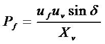
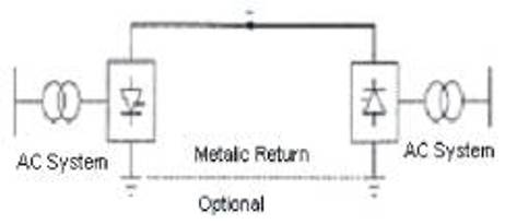
Figure 2. HVDC Mono-polar link System
uv is the controlled voltage source from the AC side and Active power flow Pf neglecting losses in the phase reactor, where uf is the ac voltage on the secondary side of the transformer and uv is the voltage generated by the VSC, Xv is the reactance of the VSC.
The reactive power and the dc current of VSC is given by.
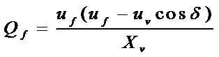
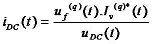
Where Iv(q) is the VSC source current and iDC and uDC are the VSC dc current and voltage respectively.
Normally, the DC transmission line of VSC-HVDC can be Composed by:
(i) DC cable
(ii) DC overhead line
The choice between the use of cables and overhead lines is determined by environment constraints as well as an overall optimization considering the total capital cost and the reliability of the transmission system. Generally, the environment impact of cable will be much smaller compared with overhead line. The common fault types for DC transmission line are line to- ground fault and line-to-line fault. Because faults of cables are usually caused by external mechanical stress, therefore the faults are generally permanent, for which a lengthy repair is needed. The converters should be stopped immediately while a cable fault is detected. But for overhead line, the faults are always caused by lightning strikes and pollution; faults along the line are likely to be temporary, which demands a fault restoration after the fault clearance.
The line-to-ground fault means insulation failure between one DC conductor and ground, and for overhead line, the fault is usually temporary which is caused by lightning strikes and pollution. The primary fault consequence is the direct discharging of the capacitor on faulty pole. The voltage of the healthy pole will rise to 2.p.u because of the action of the DC voltage controller, which will impose an overvoltage on healthy pole capacitor even if the restriction of DC pole arrestor is considered, as in [1]. For DC cable, the system does not need to be restored due to the permanence of the fault, but for Overhead line, the restoration of the system should be considered.
Considering the line-to-ground fault under bipolar system, the faulty pole capacitor suffers an over current due to the rapid discharging through fault position. The voltage of DC capacitor will also decrease to a very low level, as shown in Figure 3.The healthy pole capacitor will be charged to 2.p.u because of the DC voltage controller. Note that for overhead line, even if the fault is temporary, the unbalance of capacitor voltage cannot be restored after fault clearance.
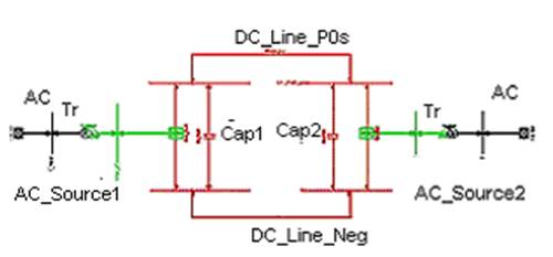
Figure 3. VSC - HVDC Configuration
The line-to-line fault means insulation failure between the two DC conductors. The capacitor will be rapidly discharged due to fault, simultaneously the ac system will be three phases short-circuited through fault point, as shown in Figure 4. Obviously the valve will be over current stressed.
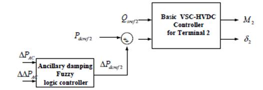
Figure 4. General VSC-HVDC Controller for Terminal 2
The fault demands that both converters should be blocked, but we should note that, the ac system is still short-circuited through the VSC Free Wheeling Diodes (FWD), which means the ac system will continue to feed current into the fault even if the converter is blocked. To avoid this, besides blocking the Converters, the DC line is also needed to be isolated from the ac system by tripping ac breakers to enable the air insulation to de-ionize. Another method is to introduce DC breakers and open these when a fault is detected.
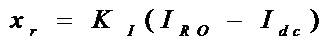
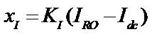
The design of steady state controller for VSC-HVDC system is mainly based on its mathematical model. However, the ancillary damping controller for VSC-HVDC is easy to be influenced by the external interference of the uncertainty, such as the random fluctuation of the load and disturbance of different faults in the two area. It is important to design the VSC-HVDC controllers to be adaptive for different conditions of the system. This paper presents a fuzzy logic ancillary damping control added to a normal steady state controller of VSC-HVDC. The knowledge based on fuzzy control [18], outperform the linear control in many of the cases exposed before, a reason of this is that the human knowledge adds several types of information and can mix different control strategies that can not be added in an analytical control law and do not need an accurate mathematical model.
The Knowledge-based fuzzy control uses the experience and the knowledge of an expert about the system behavior. A kind of Knowledge-based fuzzy control is the rule-based fuzzy control, where the human knowledge is approximated by means of linguistic fuzzy rules in the form if-then, which describes the control action that would be made for a human operator. Due to the nonlinear behavior showed by the converter, to the failed attempt of design a linear control, and supported in the advantage of the fuzzy control exposed before, a nonlinear fuzzy control might be desirable to effectively damping area oscillation, by dynamically adjust the active power reference of the normal steady state controller. The control proposed for the ancillary fuzzy logic controllers is a Mamdani controller, Because of it is usually used as feedback controller. The rulebase represents a static mapping between the antecedent and the consequent variables.
Fuzzy sets must be defined for each input and output variable, as shown in Figure 5. Five fuzzy subsets are needed for the antecedent error. For Both DPAC and D DPAC, the subsets are: Negative Big (NB), Negative Small (NS), Zero Error (Z), and Positive Small (PS), and Positive Big (PB). Figure 6. the fuzzy subsets used in the consequent were just like the antecedent.
The membership functions in Figure 8 were tuned searching the Minimum error in steady state and the minimum oscillation in steady transitory by trial and error method, by using the toolbox FIS of Mat lab. The rule base represents the knowledge obtained from the behavior of the system is summarized in Table I, which was proposed after getting knowledge about the dynamic and steady state behavior of the system.
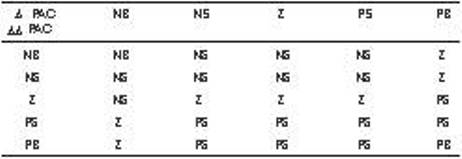
Table 1. Rule base of ADFC
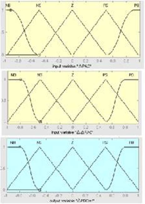
Figure 5. Member faction of PAC ,PAC and PDCref
The rectifier and the inverter are 12-pulse converters using two Universal Bridge blocks connected in series. The converters are interconnected through a 110-km line and 0.78H smoothing reactors as shown in Figure 5 the converter transformers (Wye grounded/Wye/Delta) are modeled with Three-Phase Transformer (Three-Winding) blocks. The transformer tap changers are not simulated. The tap position is rather at a fixed position determined by a multiplication factor applied to the primary nominal voltage of the converter transformers (0.90 on the rectifier side, 0.96 on the inverter side).
The HVDC transmission link uses 12-pulse thyristor converters. Two sets of 6-pulse converters are needed for the implementation stage. AC filters and DC filters are also required to minimize harmonics.
The firing-angle control system is configured based on two 6-pulse converters in series, one of which is operated as a modified HVDC bridge. The HVDC power converters with thyristor valves will be assembled in a converter bridge of twelve pulse configuration. This is accomplished by star-star connection and star-delta connection. Reduction of harmonic effects is another factor of investigation. Here, MATLAB/SIMULINK program is used as the simulation tool.
Two 6-pulse Graetz bridges are connected in series to form a 12-pulse converter. The two 6-pulse bridges are 275Kv, 60 Hz totally identical except there is an in phase shift of 30° for the AC supply voltages. Some of the harmonic effects are cancelled out with the presence of 30° phase shift. The harmonic reduction can be done with the help of filters.
The firing angles are always maintained at almost constant or as low as possible so that the voltage control can be carried out. Six or eight of equal rating bridges are the best way to control the DC voltage. More than these numbers of series bridges are not preferable due to the increase in harmonic content. The control of power can be achieved by two ways i.e., by controlling the current or by controlling the voltage. It is crucial to maintain the voltage in the DC link constant and only adjust the current to minimize the power loss. The rectifier station is responsible for current control and inverter is used to regulate the DC voltage. Firing angle at rectifier station and extinction angle at inverter station are varied to examine the system performance and the characteristics of the HVDC system. Both AC and DC filters act as large capacitors at fundamental frequency. Besides, the filters provide reactive power compensation for the rectifier consumption because of the firing angle.
Figure 5, Shows VSC-HVDC system with Fuzzy the real power Output in the line is controlled to obtain steady-state condition. When system harmonics is introduced the weak power transmission normally occurring in long transmission lines was studied using MATALB. The diagram given in Figure 5 shows the computational layout of VSC-HVDC which is simulated for damping system harmonics and rectification as well as with power inversion in its converters. Simulation of VSC-HVDC System carried out using MATLAB / SIMULINK with Fuzzy and Simulation results was presented to create oscillations with the line current and power waveforms during the power transmission. Figure 6 to 12 shows the simulation results of VSC-HVDC system when three phase, Line to Ground and double line ground Fault. From the simulations results, it is observed that when different types of faults i.e. three phase, Line to Ground and Double Line to ground occurs the system are having more oscillations and system takes more time to reach the steady state operation. By using Fuzzy the system reduces oscillation and thereby enhanced the power transfer capability of VSC-HVDC system.
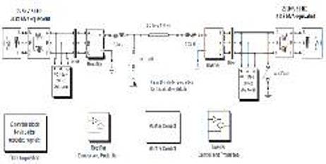
Figure 5a. Simulink diagram of the HVDC Circuit
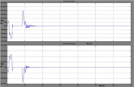
Figure 6. Simulation Result for Line active and Line Reactive Powers of HVDC System when three phase Fault occurs on Inverter
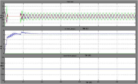
Figure 7. Simulation Result HVDC System when three Phase fault occurs on Inverter
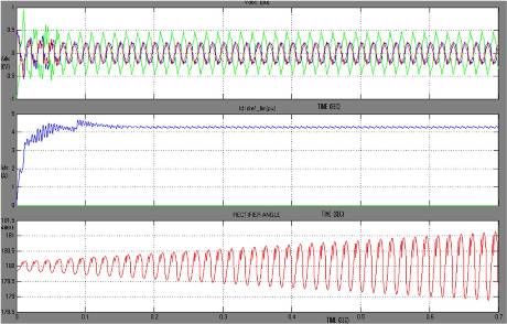
Figure 8. Simulation Result HVDC System when three phase fault occurs on Converter
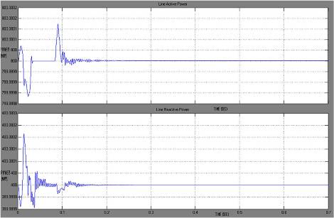
Figure 9. Simulation Result for Line active and Line reactive powers of HVDC system when Line to Ground fault occurs on Inverter
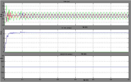
Figure 10. Simulation Result HVDC system when Line to Ground fault occurs on Inverter
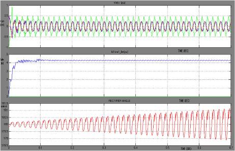
Figure 11. Simulation Result HVDC system when Line to Ground fault occurs on Converter
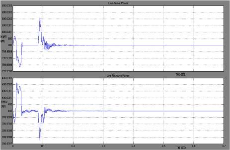
Figure 12. Simulation Result for Line active and Line reactive powers of HVDC system when Double Line to Ground fault occurs on Inverter
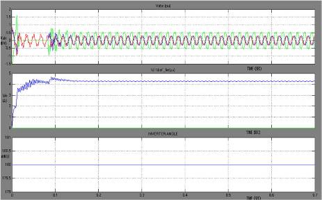
Figure 13. Simulation Result HVDC system when Double line to Ground fault occurs on Inverter
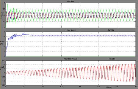
Figure 14. Simulation Result HVDC system when Double Line to Ground fault occurs on Converter
VSC-HVDC is an advanced and hopeful transmission technology and fuzzy control is an effective method used to control nonlinear system without the need to resort to complicated mathematical models. In this paper, an ancillary damping fuzzy control is proposed to change the active power reference dynamically. System stability is improved with the proposed ancillary damping fuzzy control are verified in MATLAB/SIMULINK simulation. Under normal and fault condition the controller is tested which gives the satisfactory result. Simulation result shows that with proposed control strategy, quick response and dynamic stability have been achieved for any kind of changes and high level control accuracy is attained at different operating condition.