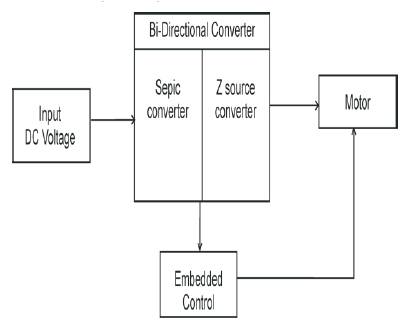
Figure 1. Block diagram of Sepic and Z-Source Converter
This paper presents the sepic converter and z converter performance are analyzed, sepic converter produces very high voltage for giving small Input voltage, reduce the total harmonic distortion to improve the efficiency form 89% to 95%. The matlab version 7.3 using for simulation results at constant frequency is used in UPS, high density discharge lamp fuel cell system and photovoltaic systems. Hardware is closely agree with the simulation result sepic converter is more advantages than z-converter they are high step up capability, design flexibility and distributed voltage stress can be achieved. To maintain continuous Input current and clamped voltage stress on switch.
Switch conduction losses are low, Transformer utilization is the best in the full bridge converter and Input current ripple is lowest due to interleaved operation. [1]. To produce constant input continous current and constant frequency and utilized in high voltage operation. It is noted that other converters, which has a inductor and a switch as an input stage can be integrated[2]. Modified Isolated full bridge bidirectional Dc-Dc convertor has high efficiency simple circuit and low cost peak to peak current ripples be 20% of the Indicator currents under full power[3] while the converter is required to operate over a wide input- voltage range, high converter efficiency is particularly important at minimum input voltage and maximum power. With the storage Inductor placed at the input side, input ripple current is inherently low[4]. The principle merits of the switching converter are its high conversion efficiency and its high power packing density, which result in significant control circuits, and noise or electromagnetic Interference (EMI) filters. The Input filter is required in some applications[5]. It is two start up schemes for the activeclamp Isolated full bridge boost converter in suppressing the in rush current that is normally found in the boost mode start up. Operation of two mode schemes can achieve smooth output voltage transition from start-up mode to normal boost mode operation and are suitable for high power Isolated boost converters[6].
All switches realize zero voltage switching in a wide range of load variation while Input or voltage varies, phase shift plus pulse width modulation control reduces the circulating current. This control method to the energy conversion is carried out[7]. The efficiency of non- Isolated bidirectional DC-DC converters, with or without coupled Inductors, can be improved. They are implemented with zero voltage switching [3-8]. Effect of switching operation in asymmetry none form on an Isolated full bridge boost converter to reduce the losses and increased the efficiency for one of the way to improve the efficiency [9]. The ripple current is suppressed by the common mode voltage control of the DC-DC converter. The current ripples are provided by the energy buffer capacitor. The buffer capacitor is used as an energy storage element of the active filter[10].
Switching frequency of the input current ig is quadrupled and the current ripple is reduced due to interleaved structure and phase shifted switching of the paralleled converters. In output voltage (Vo ) is quadrupled and the voltage is ripple is reduced due to the summation of the four capacitor voltage[11]. Zero voltage Transition- pulse width modulation (PWM) converter, main switch turns on with zero voltage transition [ZVT] perfectly with the help of a snubber cell with paralleled resonance compared to the other converters, the proposed converter has the advantages of size, number of components, and reduce the cost the value of subber Inductances are not magnetically coupled [12]. Distortions of feedback signals due to converter switching can be avoided by over sampling and filtering of the filter capacitor voltage[13]. Figure 1 shows the block diagram of the combination of sepic converter and z- source Isolated converter. The Input Dc. voltage is applied to sepic/ Isolated z- converter. Filter circuit is produced in the output RC filter is superior in the sepic converter II filter is superior in the Isolated boost zsource converted. The load DC Connected with DC motor. It is embedded circuit is fabricated in the hardware the result is closely agree with the simulation result.
Figure 1. Block diagram of Sepic and Z-Source Converter
This converter can be short and open circuited without damaging switching devices. It is very strong to EMI and its robustness and reliability is significantly Improved[14]. Sepic converters are usually designed with coupled Inductors to reduce the production costs and to reduce the current ripple. sepic converters maintain the output voltage polarity same to the input voltage[15]. A interleaved current fed full bridge DC/DC converter with parallel input and series output connection. Input current ripple is reduced[16] very low levels of parasitic circuit Inductance are achieved in isolated boost converters for high power low voltage[17]. The resonate full bridge Dc- DC converter is produce high efficiency in the range of medium to high voltage[18].
The Input voltage is applied to bidirectional sepic converter/ z source Isolated dc-dc converter Sepic converter is more predominant compared to the Isolated z- source quasi resonance converter. Sepic converter Isolated transformer is ideal but there is leakage inductance losses in z source resonance converter.
Both the converter is fabricated with microcontroller and verified both the circuit. Sepic converter is high speed non- Isolated DC-DC converter. To the input DC voltage is applied to the Boost converter. When the transformer Isolation are ideal there is reduce the number of switches to operate the medium to high DC voltage Range. When sepic converter is produce high efficiency is compared to the series resonant converter. Sepic Integrated circuit is shown in Figure (2). Isolated full bridge bidirectional Dc-Dc converter is initially operated. There is more switching losses, conduction losses and correspondingly reduce the efficiency. To design the z- source resonance converter Figure (4) to improve the efficiency is not best competent of the sepic converter.
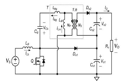
Figure 2. SIB (SEPIC Integrated Boost) converter
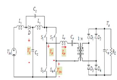
Figure 3. Proposed Z-source Series resonant
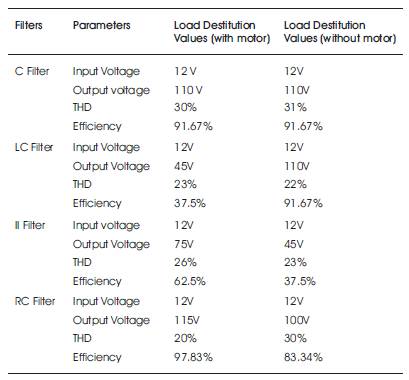
Table 1. Comparison of Passive Filter
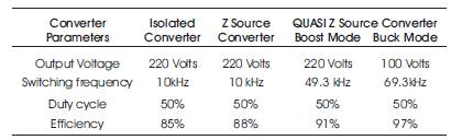
Table 2. Comparison of Isolated and Z-source Converter
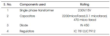
Table 3. Ratings of Components Used in Power Circuit
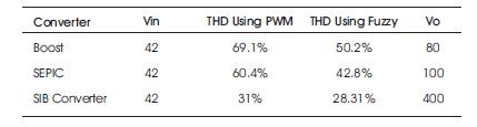
Table 4. THD Comparsion
Output voltage is less than the input voltage which Shows the equation (1) Vo = output voltage, Vin = input voltage,δ or D = duty cycle
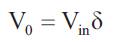
Output voltage is greater than the input voltage which shows the relation in equation (2) Vo = output voltage, Vin =input voltage, δ or D = duty cycle
Discontinues conduction mode on time which shows the relation in equation (3) Δ I = ripple current in amps, L=inductance in Henry and ton = on time
Output voltage is less than input voltage energy is stored in the magnetic field voltage across and the current flowing through the capacitor is Shows the relation in equation (4) Vc = capacitor voltage, Ic = capacitor current.
Open loop voltage conversion ratio in the discontinuous mode if the load resistance is greater than the critical resistance. Shows the relation in equation (5) Lc = Critical resistance
where L ≤ Lc
The efficiency of the converter disregarding any fluctuation of the output and input voltage Shows the relation in equation (6) Po = output power, Pin = input power and η =efficiency
Energy stored in the magnetic field Shows the relation in equation (7) E = Energy.
Simulation circuit is make it with the help of Matlab Version7.3.the isolated full bridge. Bidirectional DC-DC Converter pulse and voltage across switch is shown in Figure 3(a). Figure 3(b) show the plots of converter output voltage in boost mode and efficiency range is 89%. In boost mode the resonant frequency is 49300Hz, the converter output voltage is 220V. Efficiency of converter isolated full bridge bidirectional converter (Boost mode) is shown in Figure 3(c). In buck mode the resonant frequency is 69300Hz, the converter output voltage is 100V is Shown in Figure 3(d). Simulation result of efficiency of z source resonant converter (Buck Mode) Efficiency of converter isolated full bridge bidirectional converter (Buck mode) is shown in Figure 3(e). The simulation diagram of the sepic converter with CLC filter is shown in Figure 3(f). RC filter sepic converter is superior among all passive filter in motor analysis of the parameter s are speed, torque current and Voltage are shown in Figure 3(g),(h),(i)and (j)
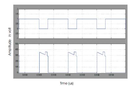
Figure 3(a). Pulse And Voltage across Boost Switch
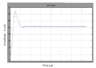
Figure 3(b). Output voltage of isolated full bridge bidirectional converter (Boost mode)
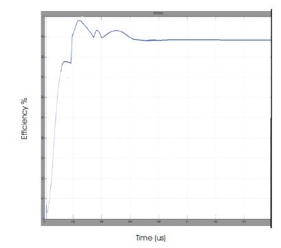
Figure 3(c). Efficiency Vs Time (Boost mode)
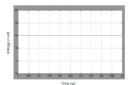
Figure 3(d). Output Voltage in buck
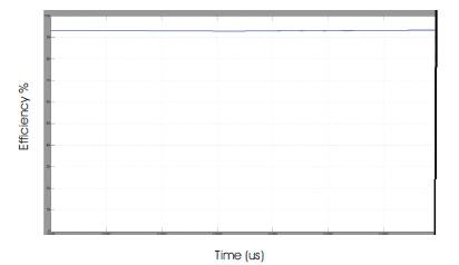
Figure 3(e). Efficiency of converter isolated full bridge bidirectional converter (Buck mode)
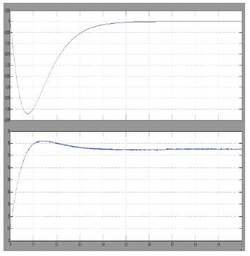
Figure 3(f). Simulation of SIB converter with π-filter
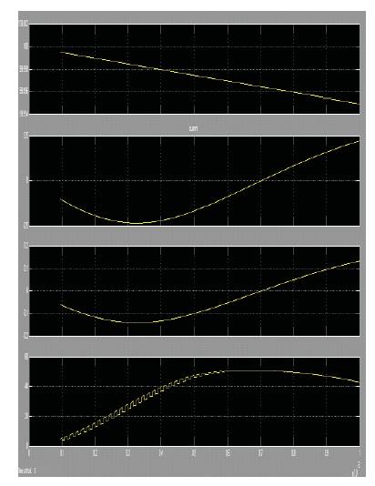
Figure 3(g),(h),(i)and (j)speed,torque,current and Voltage
The overall view of the Isolated boost z source quasi resonant converter hardware kit is shown in Figure 4(a).
Motor Ratings
Voltage = 230V
Current = 1.5A
Speed = 1500 rpm
Hp = 1/8
Output Power = 94.25 watts
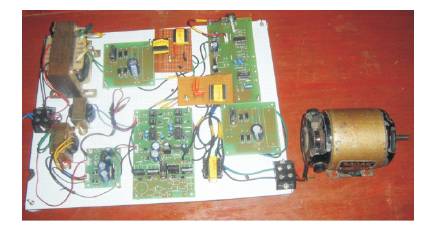
Figure 4(a) Over View of the Project
This Paper is mainly focused on an example of the step-up DC/DC converter with high-frequency isolation for the distributed power generation systems. The topologies are intended for applications with widely varying input voltage and stabilized output voltage and when the galvanic separation of the input and output sides is required. The high-frequency transformer stack is responsible for providing the input/output galvanic isolation demanded in many applications. The operating principle, converter design methodology and simulation results were presented and analyzed. The comparative analysis for different converter configurations such as power level, efficiency level, switching frequency level and time for steady state response were presented. The proposed converters can achieve good efficiency over the entire input and load ranges in simulation and also the Experimental results also verified.
The Overall view of the prototype Model is shown in Figure 4(a). In boost mode the input voltage is 30V, output voltage is 60V is shown in Figure 4(b). In buck mode the input voltage is 50 V, the output voltage is 30 V is shown in Figure 4 ( c). The entire hardware is fabricated using Microcontroller. Only 35 single-word instructions to learn All single-cycle instructions except for program branches, which are two-cycle Operating speed: DC – 20 MHz clock input DC – 200 ns instruction cycle Up to 8K x 14 words of Flash Program Memory, Up to 368 x 8 bytes of Data Memory (RAM), Up to 256 x 8 bytes of EEPROM Data MemoryPin out compatible to other 28-pin or 40/44- pinPIC16CXXX and PIC16FXXX microcontrollers. The IR2112(S) is a high voltage, high speed power MOSFET and IGBT driver with independent high and low side referenced output channels. Proprietary HVIC and latch immune CMOS technologies enable ruggedized monolithic construction. Logic inputs are compatible with standard CMOS or LSTTL outputs, down to 3.3V logic. The output drivers feature a high pulse current buffer stage designed for minimum driver cross conduction. Propagation delays are matched to simplify use in high frequency applications. The floating channel can be used to drive an N-channel power MOSFET or IGBT in the high side configuration which operates up to 600 v.
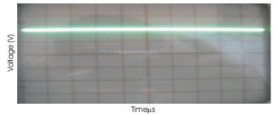
Figure 4(b). Output Voltage Waveform (Boost
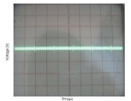
Figure 4(c). Output Voltage Waveform (Buck)

Figure 4(d). Output Voltage (Boost Mode) Oterf Sepic Converter
High speed sepic converter is reduce the switching losses, conduction losses, reduce the harmonic content in high voltage operation efficiency is high compared (94%) to the Isolated z source quasi resonance converter. In bidirectional dc-dc converter is used in fuel cell battery Hospitalization UPS, telecommunication high density performance. Frequency is operated at maximum 70kHz. The proposed converters compare the sepic Integrated boost converter can achieve high efficiency 89%than the Isolated z –source quasi reservance converter. The experimental result is closely agree with the simulation result.