Figure 1. Existing Model
Now a days the requirement for renewable energy power production is increasing due to scarcity of conventional energy resource. So, one of the best renewable energy resource for production of electrical energy is wind. As most of the loads are lagging loads, losses will be more due to low power factor. In this Study, the authors suggest that even though capacitor bank is connected to compensate reactive power, and maintain voltage stability, there is no constant required power factor at all loads. Due to connection of capacitor in steps using capacitor bank, there is over compensation. So, power factor is low. So, in this paper they propose “Thy ristor Controlled Capacitor” to improve power factor in windmill power plant. The Expected results were obtained by using MATLAB soft ware tool. The data is collected from Wind mill power plant maintained by DECCAN CEMENTS LTD. located at RAMAGIRI, Anantapur (Dist), Andhra Pradesh, India.
The conventional energy resources are getting scared day by day. So, if this continues then there will be no conventional energy resources for future generations. So, it is the time to go for non conventional energy resources. So, world wide the interest is raising for production of power from renewable energy resources. In particular wind energy is more preferable because, wind energy is more cheap compared to solar, clean compared to biomass, also wind energy is more reliable compared to remaining energy resources. Power generation through wind has an edge because of its technological maturity, good infrastructure and relative cost competitiveness. Wind energy is expected to play an increasingly important role in the future national energy scene. Wind turbines convert the kinetic energy of the wind to electrical energy by rotating the blades. At good windy sites, it is already competitive with that of traditional fossil fuel generation technologies. So, many private companies are also entering into the power generation by renewable energy resources field to acquire more gain and to fulfill their company minimum needs. As these renewable energy resources are echo friendly, Government of India is also giving more preference to increase renewable energy power generation. So, Ministry of Non-conventional Energy Sources (MNES), Indian Renewable Energy Development Agency (IREDA) and the wind industry are working together to accomplish these improvements through various research and development programs. So, in recent years the research is increasing in wind power generating plants especially in areas where wind energy is more flexible to produce power. So one of the more flexible place in Andhra Pradesh is Ramagiri located in Anantapur District.
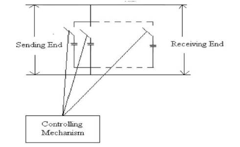
The existing power factor improvement technique is by employing capacitor bank as shown in Figure 1.
Figure 1. Existing Model
In this method a program was written to add capacitor in steps according to the reactive power requirement i.e. in proposed plant the for each step 25 KVAR will be added at a time up to the reactive requirement of 0 to 25KVAR. Beyond 25 KVAR as per program, one more capacitor will be added i.e. one more 25 KVAR. So totally 50 KVAR will be added for reactive power requirement of 25 to 50 KVAR. Due to this even though the requirement is 9 or 10 KVAR the system can't add 10KVAR so, it will add a 25 KVAR. Due to this mechanism over compensation is occurring. The study has shown that due to over compensation, power factor can't be unity, also. It is not stable at all loads. So, have proposed a new technique to improve power factor in the same power plant by using “Thyristor controlled capacitor”. The new approach is as shown below.
The new proposed power factor improvement technique is as shown in Figure 2.
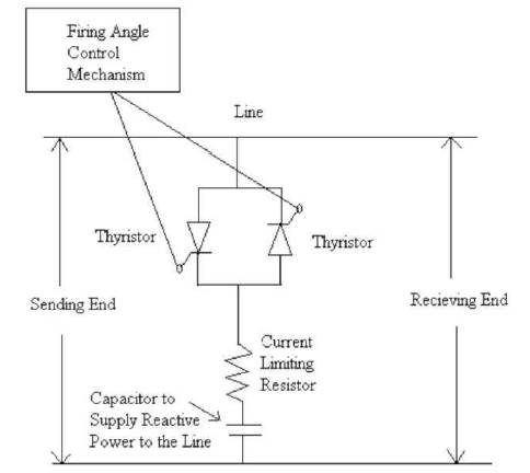
Figure 2. Proposed Model
By using this circuit diagram, the concept of capacitor addition can be explained in the Figure 3.
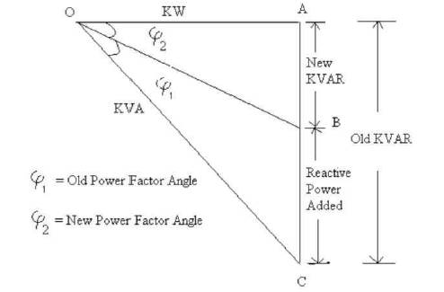
Figure 3. Power Triangle
From the above diagram OA is the Load applied on the power system. φ1 is old power factor angle before application of the reactive power. φ2 is power factor angle after application of the capacitor. In Old scheme, BC will not be proper to get φ2 . So in the new control scheme the capacitor energy supply can be controlled by using Thyristor. Whenever firing angle of the Thyristor is varied, then voltage supplied by the capacitor will be varied so that the reactive power supplied by the capacitor will be varied. A resistance is used in series with the capacitor to limit the current flowing through the capacitor. The main use of resistor is to protect the capacitor from damages of high current.
The Equations governing the circuit diagram are:
Current passing through the circuit is given by
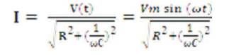
ω = 2πf,
f= frequency of the sinusoidal voltage
t= time instant
α= Firing angle of the Thyristor
Vm= Peak voltage of the sinusoidal voltage waveform
V (t) = Voltage at time instant t
Voltage of the capacitor Vc= V (t) - IR
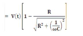
Let as assume constant K
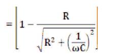
Then Vc= (Vm sin (α)) x K
But the energy supplied by the capacitor is
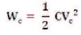
This is equal to the reactive power required by the power system. So,
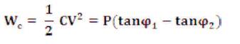
By substituting Vc Equation we will get
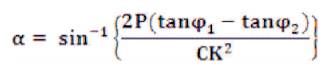
By using above formula we will get firing angle required to get required reactive power compensation.
The new power factor can be obtained by using below formula,
New power factor angle φ2
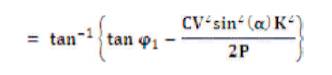
New power factor is cos (φ2 )
So, from the above formula, we can control the reactive power added to the system by using Thyristor controlled capacitor. By employing above method, authors eliminate the over compensation occurred in the previous case.
The expected result for the proposed model was obtained by using MATLAB code. The new results were compared with old values for the same load and power factors.
The load in KW and power factors were taken from the on line data collected from the windmill power station
The data collected from windmill power station located in ANANTAPUR (dist) is shown in Table 1.
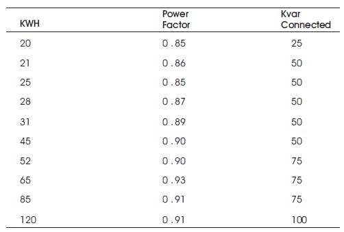
Table 1. Power Factors Obtained for Existing Model
From the results the plot drawn between kilowatt hour and power factor is as shown in Figure 4.
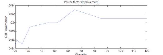
Figure 4. Plot of Existing Model
From the graph they can observe that there are fluctuations in the power factor, because of over compensation occurred in the system due to the sudden addition of capacitor in steps by using mechanical switch. Hence by employing new technique we can obtain unity constant power factor at all load because in this new approach capacitor added is optimum. This can be achieved by adding Thyristors in series with the capacitor. In this technique the same KWH load is utilized for comparison purpose. By using new method the following results are obtained and it is shown in Table 2.
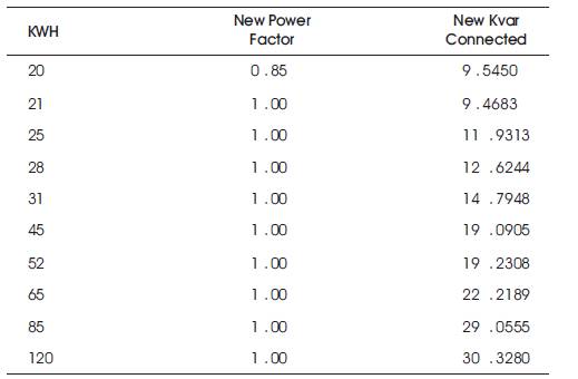
Table 2. Power Factors Obtained for Proposed Model
From this Table 1 they can observe that the KVAR connected is saved by using new approach and the power factor is maintained at unity for all loads except at initial load. This delay in initial load is due to the starting storage time of the capacitor The comparison plot drawn between KWH and power factors are as shown in Figure 5.
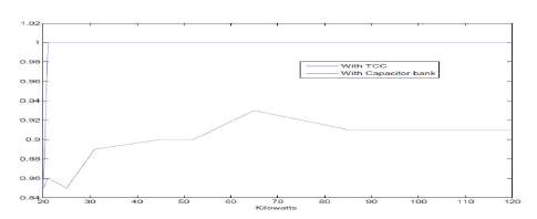
Figure 5. Plot of Comparison for Existing & Proposed Models
“The devices are assumed as ideal”
Resistance =1KΏ.
Capacitance value calculated from the bank but for the same capacitance by changing voltage we can change the reactive power added into the network
Voltage is assumed to be within limits
In recent years it is very most important to concentrate on renewable energy resources. In renewable energy resources wind energy is most reliable and cheap in cost.
In any power system, power factor improvement is most important. As we know due to low power factor, losses will be more.
Hence in this paper the authors concentrated on power factor improvement in windmill power station. In recent years in FACTS devices plays vital role in compensation of reactive power in power systems. Hence in this paper, one of the FACTS devices “Thyristor Controlled Capacitor” is utilized.
From the old method employed in RAMAGIRI windmill power station it is observed that, due to capacitor bank, there is fluctuation in power factor also it is not maintaining Unity Power Factor. So they have proposed new approach to improve power factor improvement technique by using TCC. We have obtained the required result by using new approach, this was observed by using MATLAB software programming and the results were shown.