[1]
Because of the nonlinear magnetic structure and time varying motor parameters, the traditional controllers like PI, PD and PID are insufficient in Switched Reluctance Motor (SRM) control. A strategy of hybrid Fuzzy-PI control for switched reluctance motors is presented in this paper. The strategy of fuzzy logic controller and PI controller is combined to realize the speed adjustment. The hybrid fuzzy-PI controller adopts fuzzy logic control when the speed error is big, and adopts PI control when the error is small. Simulation results indicate that this hybrid control strategy overcomes the steady state error of speed in classical fuzzy controller, and the paradox between the response time and overshoot of speed is managed. This system has a good anti-interference performance.
The Switched Reluctance Motor (SRM) is a doubly salient machine in which torque is produced by the tendency of the rotor to move to a position where the inductance of the excited windings is maximized. The simple mechanical construction is one of the main attractive features because it has no windings or permanent magnets on the rotor and thus, manufacturing cost appears to be lower compared to other motor types [1]. SRM has the advantages of simple structure, low cost and high efficiency. Along with those advantages SRM has a nonlinear magnetic structure and motor parameters are time varying. Because of these features, traditional controllers like PI (Proportional Integral), PD (Proportional Derivative), PID (Proportional Integral Derivative) are insufficient in SRM control. Hence, non-linear controllers are needed in SRM control.
Fuzzy control, widely used in engineering field at present, is an intelligent control method, and it does not require accurate mathematic model of controlled device and makes use at people's experience in adopting a control strategy. Its dynamic quality is better than PI control method [2]. But in fact two-input single output fuzzy controller is a PD controller with steady-state error [3]. In order to solve this problem, fuzzy-PI compound control strategy is presented in this paper. The controller adopts fuzzy logic control when the speed error is big and adopts PI control when the error is small. Simulation results indicate that additional integral action can overcome steady-state error, and it is better than fuzzy controller or PI controller.
The phase inductance of SRM, which changes periodically with the rotor position, can be expressed as a Fourier series with respect to rotor position [6][7].
where Nr is the number of rotor poles.
A three-dimensional (3-D) plot of inductance shown in Figure 1 depicts the profile of inductance variation with rotor position and phase current. At 0o and 60o , phase A is at its aligned positions and has the highest value of inductance. It decreases when the phase current increases. At 30o , phase A is at its unaligned position and has lowest value of inductance. The inductance at unaligned position does not change much with the phase current and can be treated as a constant. The inductance at midway and aligned position decrease when current increases due to saturation. The torque equation of SRM is given by [7]
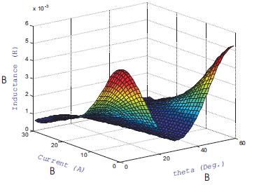
Figure 1. Profile of Nonlinear phase Inductance
The Figure 2 shows the torque variation with the rotor angular position at different values of phase current. Since the inductance gradient is negative from 0˚ to 30˚ the torque is negative and the inductance gradient is positive from 30˚ to 60˚ the torque is positive. The torque-speed equation can be expressed as
where J is the moment of inertia of rotor, Te is the electromagnetic torque, and TI is the load torque. The electromagnetic torque, Te can be computed as follows,
where Te,j is the electromagnetic torque of the jth phase and n is the number of phases.
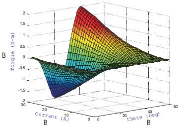
Figure 2. Profile of Phase Torque
Figure 3 shows the block diagram of the closed loop speed control of SRM. The core loop is the direct torque controller. In speed control application an outer loop is added to the torque controller. There are many choices for this speed controller, such as PI controller, fuzzy logic controller, adaptive controller, artificial neutral network controller and so on [2] [4] [5]. Undoubtedly, they can achieve different system performances. In this paper, the Hybrid Fuzzy-PI controller is presented used as the speed controller.
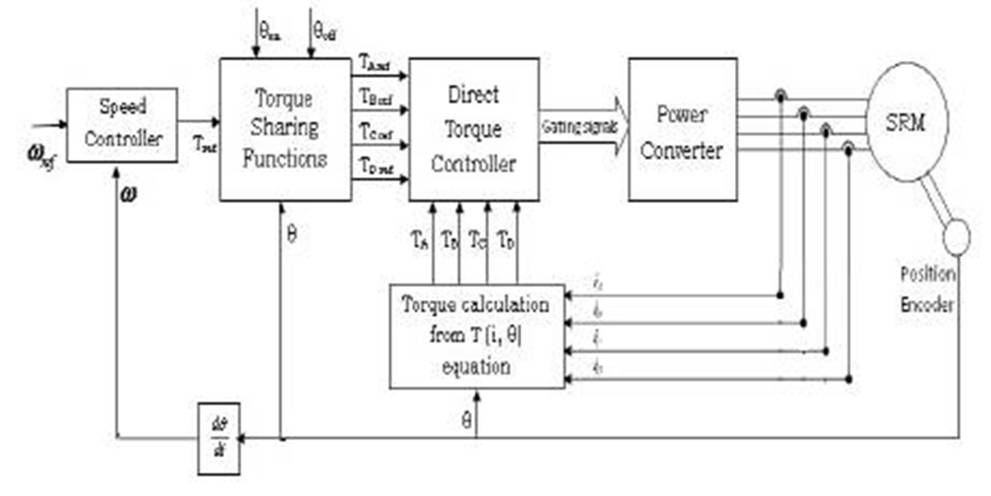
Figure 3. Closed loop Speed Control of SRM
The block diagram of the hybrid fuzzy-PI controller is shown in Figure 4. The fuzzy-PI compound control adds in integral action based on fuzzy control method. This system is a dual-input single output two-dimensional fuzzy controller. Speed error and speed error derivative are the systems inputs, and reference torque of inner loop is system output.
In the fuzzy processing of input data, the fuzzy controller regards the smaller as 'Zero'. So there is a control blind zone, which results in steady state error [3]. In the scheme presented in this paper, when the speed error is small, the system adopts PI controller to control the blind zone, and adds integral action to system. The time of adding integral action is determined by the size of speed error.
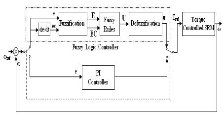
Figure 4. Hybrid Fuzzy-PI Controller
The speed goal is 500 rpm, so the basic domain of speed error and speed error derivative is [-500, 500]. The basic domain of reference torque is [-1, 1] based on SRM character, and the fuzzy domain of input (E, EC) and output (U) is [-0.65, 0.65], so the scaling factors are ke=0.65/500, kec=0.65/500, ku=1/0.65. The expressions of fuzzification are
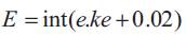

In the equation (5), when the error E=int(e.ke + 0.02) 0, |e.ke|<0.02, that e<15. So, when the speed error is to 15 rpm, the fuzzy controller regards the speed error as 'Zero' and do not adjust the speed [3]. This is the blind zone and this leads to a big steady state speed error. In this paper, fuzzy logic and PI control methods are combined to remove this blind zone. The hybrid controller adopts fuzzy control when the speed error is more than 15 rpm and adopts PI controller when the speed error is less than 15 rpm.
The proposed hybrid Fuzzy-PI control scheme for the speed control of SRM is implemented and simulated in the Matlab/Simulink environment for a four phase 8/6 switched reluctance motor. Figure 5 shows the Matlab/Simulink implementation of the proposed scheme. The hybrid controller adopts fuzzy control when the speed error is more than 15rpm and adopts PI controller when the speed error is less than 15 rpm. The output of the speed controller is applied to direct instantaneous torque controller which controls the SRM.
The results shown in Figure 6 to Figure 11 have been achieved using PI, Fuzzy and Hybrid controllers respectively with a reference speed of 500 rpm and with step changes in reference torque ie. 0.1 N.m up to 0.15 sec, 0.4 N.m from 0.15 sec to 0.25 sec, and 0.1 N.m from 0.25 sec onwards. Figure 6 shows the speed response and Figure 7 shows the torque response with PI speed controller. Figure 8 and Figure 9 show the speed response and the torque response with Fuzzy speed controller. From Figure 8, it is clear that the fuzzy controller gives better dynamic response compared to PI speed controller. In Figure 8, it can also be observed that the fuzzy controller ignores the small speed error and maintains a steady state speed error of 15 rpm.
The advantages of PI and Fuzzy controllers are combined in hybrid fuzzy-PI controller. The Figure 10 depicts the speed response and Figure 11 describes the torque response of the SRM with the proposed hybrid fuzzy-PI controller. From Figure 10, it can be observed that the hybrid converter combines the advantages of PI and Fuzzy controllers and gives better dynamic performance as well as steady state performance. The steady state speed error is reduced to zero. Figure 12 illustrates the performance of different speed controllers. The performance of PI, Fuzzy and Hybrid fuzzy-PI controllers in terms of rise time (tr), percentage peak overshoot (%Mp) and steady state error (e ) are summarized in Table I.
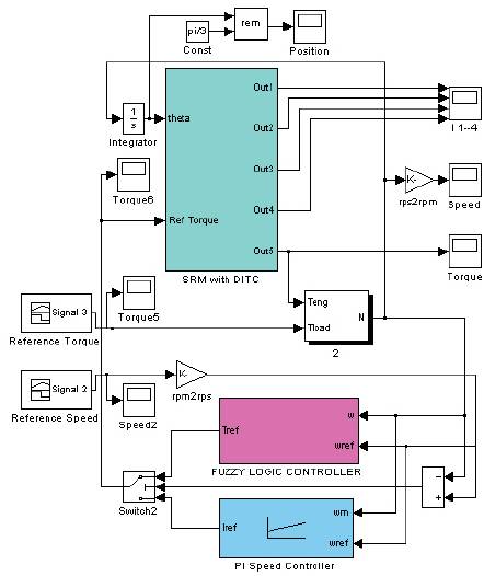
Figure 5. Matlab/Simulink Implementation
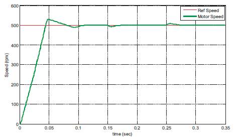
Figure 6. Speed Response with PI Controller
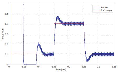
Figure 7. Torque Response with PI Controller
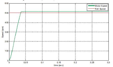
Figure 8 Speed Response with Fuzzy Controller
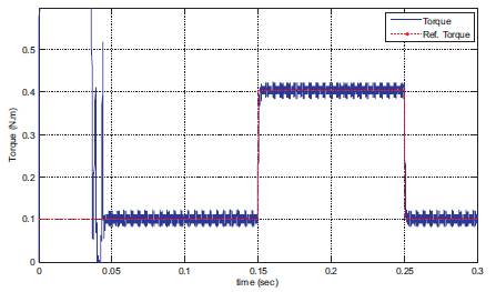
Figure 9. Torque Response with Fuzzy Controller
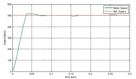
Figure 10. Speed Response with Hybrid Fuzzy-PI Controller
Figure 10. Speed Response with Hybrid Fuzzy-PI Controller
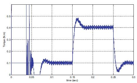
Figure 11. Torque Response with Hybrid Fuzzy-PI Controller
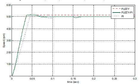
Figure 12. Comparison of speed Responses with PI, Fuzzy and Hybrid Controller
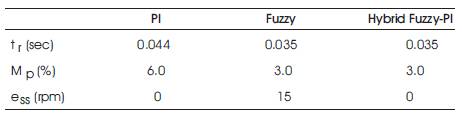
Table 1. Comparison of Different Controllers
Due to the nonlinear nature, the traditional controllers like PI, PD and PID are in sufficient in SRM control. Fuzzy logic control makes use of people's experience in adopting control strategy by using linguistic rules, and there is no need for an accurate mathematical model. Its dynamic response quality is better than PI control strategy. As the SRM is a nonlinear system, adopting fuzzy logic control strategy is a good choice, but it has a disadvantage of having steady state error and no anti-jamming capability in constant system. This paper proposes a hybrid fuzzy-PI controller for SRM which overcome the drawbacks of the PI controller and Fuzzy controller. This hybrid fuzzy-PI controller adopts fuzzy control when the speed error is more than 15 rpm and adopts PI controller when the error is less than 15 rpm. Hence, it gives better dynamic performance and also eliminates steady state error. This method manages the paradox between the response time and overshoot of speed. The dynamic and steady state performances of this hybrid controller are better than a single controller.