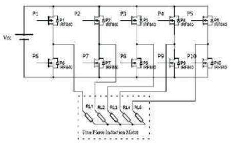
Figure 1. Circuit Diagram of FPIM
This paper aims to study the harmonics, Total Harmonic Distortion (THD) and temperature reduction of Five Phase Induction Motor (FPIM). Industries prefer power quality designs with less harmonic standards and less power dissipation. The motors must have a long lifetime for industrial applications. The superimposition of harmonic distortion affects the system completely by harming the AC output voltage waveform of the PWM (Pulse Width Modulated) inverter drive, and results in reducing its performance, lifetime of the device and overheating. Additional losses will also be induced into the system and therefore it is necessary to remove the harmonics at the output of the inverter. Many techniques are used to minimize these harmonics. Typical method to mitigate the harmonic distortion is the filter method; LC filter is the most commonly used filter to suppress the harmonics. Experimental investigation of Five Phase Inverter Drive (FPID) with LC filter with delta capacitor model is carried out to study the harmonics and THD. The obtained results are extended to study the temperature of the FPIM and compared with the predicted temperature at different locations of FPIM at low speed. It is found that there is a drastic reduction of temperature at various parts of the induction motor, which are validated by the results.
An advanced technology in power electronic system leads to the development of industrial sectors and causes fast growth in the electrical and mechanical applications. The power electronic system uses fast switching power semiconductor devices for converter system. Various Induction Motor Drives (IMD) requires Pulse Width Modulated (PWM) inverters and converters to power the motors. Most of these units are constructed with fast Switching Metal Oxide Semiconductor Field Effect Transistor (MOSFETs), Insulated-Gate Bipolar Transistor (IGBTs), intelligent modules and, smart power semiconductor devices. The three-phase induction motor is the workhorse in the industry due to its many advantages over DC motor. Advancement in power systems has introduced Multi Polyphase Systems (MPS) over three phase system, because of its dominant advantages such as less pulsations in torque, less harmonic current in the rotor, higher reliability, low DC-link current ripple, and low current per phase without increasing voltage of per phase with high torque density. The applications of Five Phase Inverter (FPI) include marine propulsion, electric aircraft, traction locomotives and, electric and hybrid vehicles ( Al-Abduallah et al., 2013; Casadei et al., 2007; Chen et al., 2013). MPSs are effectively better compared to three phase, as power delivered by MPS is more compared to three-phase for higher power and current applications like locomotives, ship propulsions, electric and hybrid vehicles. Another advantage is that torque density can be enhanced and fault tolerance is more in MPS. The system working with high power applications leads to undesired problems. It can be resolved by increasing the number of phases ( Chow et al., 2015; Councils & Recommendation 2012; Cusimano & Casolo, 2016; Dahono et al., 2010; Dahono & Rizqiawan, 2008; Dahono & Supriatna, 2009 de Morais Sousa et al., 2013).
Variable Speed Drive (VSD) is capable of adjusting speed and torque of an induction motor, as required by the designers for industrial applications. Most of the industries need VSDs for their applications such as pumps, fans, compressors etc. (Demetriades et al., 2010). The improvement of power quality has a great impact on the industrial market. The designers face cost of construction and the bulkiness of the system to improve the power quality, to operate the device for a longer time. The source of harmonics is from non-linear loads, converters, inverters and variable speed drives (Donolo et al., 2016). In non-linear loads, current is not proportional to the voltage and this leads to harmonic generation (Dugan et al., 1996). The power quality is directly linked with harmonics of the power electronic systems. As a result, it invariably introduces harmonics at the output of the converter system, which leads to an adverse effect on efficiency and power of induction motor, torque, and vibrations (Dzhankhotov & Pyrhönen, 2013). Harmonics are an integral multiple of the fundamental frequency; these harmonics superimpose on fundamental frequency creating many issues in the power electronic system. These harmonics cause distortions in the voltage and current of the inverter and converter systems (Donolo et al., 2016). It directly impacts on variations of amplitude and frequencies of the harmonic orders in integral multiples of fundamental frequency and amplitude. These integral multiples of harmonics create additional excess heat in the Inter-Modulation Distortion (IMD) (Grandi & Loncarski, 2013). This additional excess heat produced in the motor will reduce the lifespan of the IMD by damaging the stator windings. Precautions are to be taken while operating the IMD, that the maximum temperature should not reach to its permissible internal temperature, which will impact on motor's reliability and reduce motor lifespan (Hakeem et al., 2013). The goal of the researchers is to minimize the additional excess heat generated due to harmonics, experimentally in IMD. The thermal model is developed to estimate the induction motor temperature at various locations. In general, inverter generates odd harmonics of the order 1st , 3rd , 5th , 7th , 9th , 11th , 13th , 15th , 17th ....etc., in FPI, 5 and its multiple harmonic orders are absent. The present harmonic orders in FPI are 1st , 3rd , 7th , 9th , 11th , 13th , 17th etc., the dominant order of harmonic is 3rd harmonic, whose magnitude of the current is very high (Das, 2015). These harmonics never contribute an external energy for the mechanical system, instead these harmonics are simply dissipated as heat (Dugan et al., 1996).
The FPIM is experimentally constructed using MOSFETs, and control signals are generated using Microcontroller kit. The circuit diagram of FPIM is shown in Figure 1. Switching pattern and working of 10 MOSFET switches P1 – P10 are shown in Figure 2. Switches P1 – P10 are conducting for a period of 180º with a phase shift of 72º with each other. The five phase lines are represented by A, B, C, D, E and A', B', C', D', E' represents its compliment. There are 10 working modes in this switching pattern. In all the 10 modes, 3 from the upper group and 2 from the lower group will conduct and vice versa, to produce the PWM AC voltage at the output of the inverter.
Figure 1. Circuit Diagram of FPIM
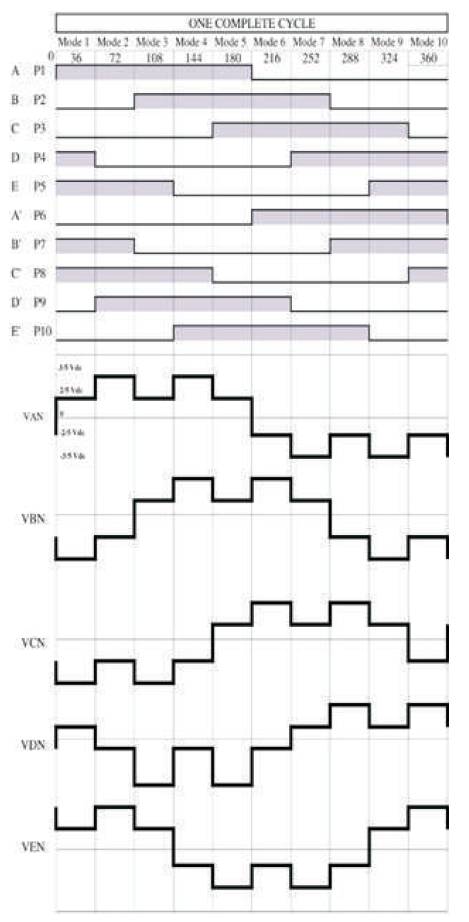
Figure 2. FPI Switching Pattern
The filter consists of inductor and capacitor which is coupled to the load from the inverter, and the filter is placed next to the source of harmonic generation. Many researchers studied and designed LC filter for different frequencies. LC filter without resistor is commonly used by the designers, because it dissipates power and converts into temperature. LC filter will offer a zero impedance channel for the tuned resonant frequency.
While designing the filters, it is mandatory to monitor maximum current ripple from the inverter due to switching action. Inductance is dependent on the inverter's maximum current ripple and capacitance value is dependent on the inverter's voltage ripple from the switching action of the switches in inverter (Jankowski et al., 2010). These shunt type filters create low impedance lane for harmonic content which attracts harmonics from the systems (Donolo et al., 2016), and avoids the coupling of harmonics to the load.
Capacitor behaves as a low impedance point where higher order harmonics and higher frequency will be absorbed (Donolo et al., 2016). Filter aims to reduce the dominant harmonic content, and other harmonics are suppressed. The resonant frequency (fR ) can be calculated using the equation (1). The FPIM with LC filter (delta type connected capacitors) is shown in Figure 3 ( Jankowski et al., 2010; Jones et al., 2010; Levi, 2008; Levi et al, 2016; Levi et al., 2007; Li et al., 2015; Calzo et al., 2015; Manjesh et al., 2013; Mohamedet al., 2013; Nauman & Hasan, 2016).
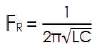
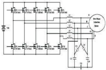
Figure 3. Circuit diagram of FPIM with LC filter (Delta type connected Capacitors)
Heat distribution in the induction motor can be calculated by convection conduction, radiation techniques (Saidur et al., 2012) using thermal model theory (Donolo et al., 2016). Temperature estimation and monitoring are necessary for power systems, for the better lifetime of a device. Thermal properties of the structures in power system at nodes are termed as thermal resistance and the energy stored in these nodes are termed as thermal capacitance. Thermal model of the FPIM is studied by Lam et al., (2014). The values of thermal capacitance and thermal resistance are determined by the thermal model shown in Figure 4 ( Tallam et al., 2015; Vazquez et al., 2015; Ye et al., 2016; Zhang et al., 2013).
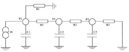
Figure 4. Thermal Model of FPIM
The parameters of induction motor used in this work are presented in Table 1. V/F control method is employed to operate the induction motor at low speed. The FPIM is operated experimentally with a fundamental frequency of 8 Hz and input voltage of 32V.
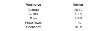
Table 1. Motor Parameters
For 8 Hz, 1st , 3rd , 7th and 9th harmonic orders are present; to remove the dominant harmonic order and higher order harmonic frequencies, LC filters with a resonant frequency 24 Hz is designed and used for experimental work. The designed values of L= 42 mH and C= 1000 μF are obtained using equation (1), hence the inductors L1- L5 = 42 mH and C1 – C5 = 1000 μF are used for the experimental work.
Programmed PWM gate pulses (control signals) are generated using a microcontroller to drive the inverter, as shown in Figure 5. The initialization of motor input parameters are shown in Table 2. The FPI output voltage and current waveform without filter and with LC filter are as shown in Figures 6 and 7 respectively.
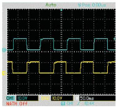
Figure 5. Gate Pulse Voltage Waveform of First Phase (A) Measured at P and P switches
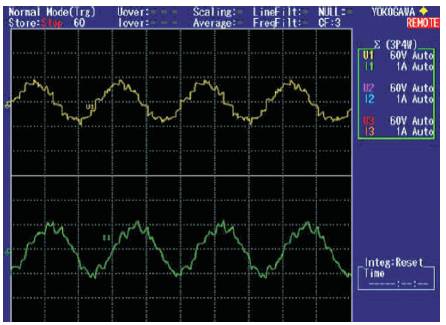
Figure 6. Output Voltage and Current Waveform of Phase A (without filter) at V =32V, f =8 Hz, Torque Load of 0.13 Nm
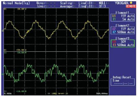
Figure 7. Output Voltage and Current Waveform of Phase A with LC Filter at V =32V, f =8 Hz, Torque Load of 0.13 Nm

Table 2. Initialization of Input Parameters
Fast Fourier Transform (FFT) analysis has been done for the inverter output voltage without and with LC filter, obtained by using power analyser, are shown in Figures 8 and 9 respectively. Overall THD of FPIM without and with LC filter are measured, and it is presented in Table 3.
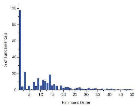
Figure 8. FFT Analysis of Inverter Output Voltage obtained by Power Analyser (without filter) at V = 32V, f = 8 Hz, Torque Load of 0.13Nm
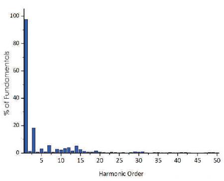
Figure 9. FFT Analysis of Inverter Output Voltage obtained by Power Analyser with LC filter at V = 32V, f = 8 Hz, Torque Load of 0.13Nm

Table 3. Overall THD of FPIM without and with LC filter at input frequency of 8 Hz
The temperature of the induction motor is measured at various parts, and the motor is operated at low speed of 213 RPM for a period of 4 hours and the temperature is also recorded. Temperature versus time graph has been plotted for FPIM without and with LC filter and are presented in Figures 10 and 11 respectively.
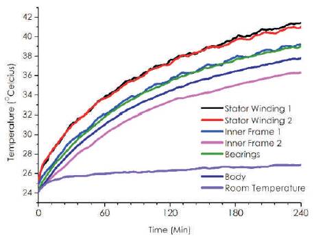
Figure 10. Measurement of Temperature of FPIM (without filter) at V = 32V, f = 8 Hz, Torque Load of 0.13Nm
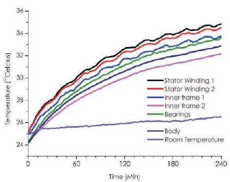
Figure 11. Measurement of Temperature of FPIM with LC Filter at V = 32V, f = 8 Hz, Torque Load of 0.13Nm
Table 4 shows the maximum temperature measured in FPIM without and with LC filter, also the temperature has been compared with predicted temperature (actual temperature obtained using thermal model).
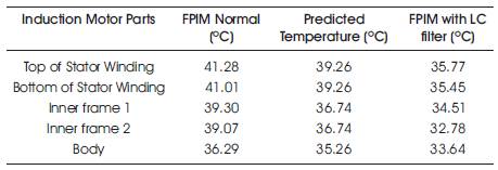
Table 4. Comparison of Maximum temperature of FPIM without filter, with LC filter, and predicted temperature
FPIM is experimentally constructed and the harmonics and THD are measured using power analyser. LC filter is designed and implemented to reduce the harmonics in FPIM operated at low speed. Harmonics and THD are suppressed by LC filter tuned to a resonant frequency of 24 Hz, to remove the dominant 3rd harmonic at the output of the inverter. The reduction of harmonics and THD has been extended to study the temperature of FPIM at various locations. It is found that the rate of rise in temperature has been minimized to 35.77º C from predicted temperature 39.26º C, which is shown in Table 4. This leads to increase in the lifetime of the windings of five-phase induction motor.