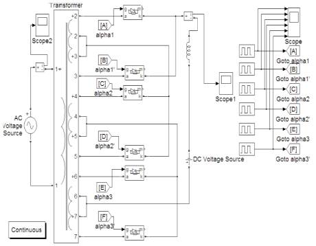
Figure1. Simulink Model of a Four Level Grid Connected Inverter
Multilevel inverters have drawn increasing attention in recent years, especially in the distributed energy resources area. Several renewable energy sources (batteries, fuel cells, solar cells, wind turbines or micro turbines) can be easily connected through a multilevel inverter to feed a load (off-grid) or interconnect to the ac grid (grid-tie) without voltage balancing problems. Moreover, multilevel inverters have a lower switching frequency than standard PWM inverters and thus have reduced switching losses. The output waveforms of multilevel inverters are in a stepped form, resulting in reduced harmonics compared to a square-wave inverter. In the present work, PIC 16F877A microcontroller based triggering circuit has been designed to be used with various levels of multilevel inverter. Multiple pulses with relative delay and requirement of a single variable dc supply (0-5V) for the control of all delay angles, makes it cost effective and simple. In addition, PIC 16F877A are cheaper with respect to other 8 bits microcontrollers available in market. It is a RISC controller with only 25 instruction sets. The Harvard architecture makes it more attractive. The simulation is done using MPLAB IDE and PROTEUS 7. Practical circuit has been designed and successfully implemented.
Multilevel converter technology is based on the synthesis of the ac voltage from several different voltage levels on the DC bus. As the number of voltage levels on the DC side increases, the synthesized output waveform adds more steps, producing a staircase wave which approaches the sinusoidal wave with minimum harmonic distortion [1],[2]. Multilevel converters are particularly useful for high power applications such as FACTS since the need of filters is reduced and the efficiency is high, as all devices switch at fundamental frequency [3], [4]. Multilevel converter topologies are also found suitable for PV applications since due to the modular structure of PV arrays different DC voltage levels can easily be provided [2], [5], [6]. Grid connected multilevel inverter with renewable energy source have reduced harmonics. Normally, thyristors in the multilevel converter/inverter are switched on by the application of a voltage signal at the gate terminal of the device. The gate voltage (Vg) is generated with the help of a gate drive circuit, which is called a firing or triggering circuit. Thus, thyristors can be switched on by a slow-rising rectified AC signal, a sharp single pulse, a constantmagnitude dc signal, or a train of high-frequency pulses [7]. The thyristor switches on as soon as Vg exceeds the critical gate trigger voltage (Vgt) level. This depends on the gate-to cathode junction temperature (Tj), anode current (ia), and the supply voltage [7]. The ideal switching signal for a thyristor should have an adequate amplitude of current for sufficient duration with a short rise time. The initial high magnitude and rapid rise of the gate current quickly turn on the device completely. Thus, carriers spread rapidly throughout the surface of blocking junction (J2). This decreases switching losses and increases the initial di/dt capability of the device. After a few microseconds, a small gate current (slightly higher than the minimum value required for triggering Igt) can be maintained [7]. Ordinarily, a continuous gate signal is not required, but inductive circuits necessitate a sustained gate signal initially, until successful triggering takes place. However, for a resistive load, a single sharp rising pulse is sufficient for triggering [8]. For high-power applications, it is a common practice to isolate the control and triggering circuits from the power circuit consisting of high power otherwise, the effects of high voltage and high current transients may cause disoperation or damage to the lowpower control and trigger circuits [7]. For this purpose, pulse transformers or opto couplers are used for low- and medium power semiconductor devices. Various circuits are used for triggering the thyristor. In the present work, PIC 16F877A microcontroller based triggering circuit has been designed to be used with various levels of multilevel inverter. The major advantage of using microcontroller for generating triggering pulses is the ease with which it can be programmed to generate a number of relative switching delay pulses for control circuit [9]. The pulses generated from microcontroller are given to the inverter through opto isolator (MOC 3021) for isolating it from the power circuit. For a four level inverter six opto isolators are required for the six thyristors. A multilevel converter/ inverter microcontroller based triggering circuits are cost effective and useful in generating feedback signals which otherwise is not possible in other types of triggering circuit topologies [9], [10].
Figure 1 shows SIMULINK model of a grid interactive inverter. The simulation work is basically done to study the THD variation of the line current with the triggering angle combination and utilise it in designing a practical microcontroller based triggering circuit. Here the triggering pulses are given from the pulse generator block of the simulink blockset. The value of inductor is 200 mH. The transformer ratio is 230V:50V:0:50V for each secondary winding. The lower leg of each converter is triggered at a phase delay of 180o to the upper leg. The battery has been used as the DC source. PV array, rectified voltage from wind turbine or any other renewable DC source can also be used instead of the battery. The line current with harmonics is shown in Figure 2. Table I shows the variation of total harmonic distortion with the variation of switching angle. It is evident from Table I, the lowest THD has been achieved for triggering configuration as α1 =105o, α2 =125o and α3 =155o. Practically, the THD is reduced further due to residual inductance of the circuit. Therefore this combination is selected for the development of the practical triggering circuit and grid interactive inverter.
Figure1. Simulink Model of a Four Level Grid Connected Inverter
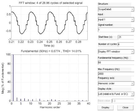
Figure 2. Line Current with THD and Harmonics.
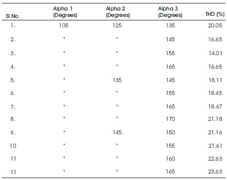
Table 1. THD Variation of the Line Current With the Triggering Angles
Figure 3(a) shows the development board with pic kit2 programmer. Figure 3(b) shows the flowchart for the generation of pulses. The triggering pulses have been generated from PIC 16F877A, a 8 bit middle level microcontroller from Microchip. PIC16F 877A is a high Performance RISC microcontroller with only 35 single word instructions. All are single cycle instructions except for program branches, which are two-cycle. The Operating speed for 20 MHz clock input is 200 ns per instruction cycle [11].
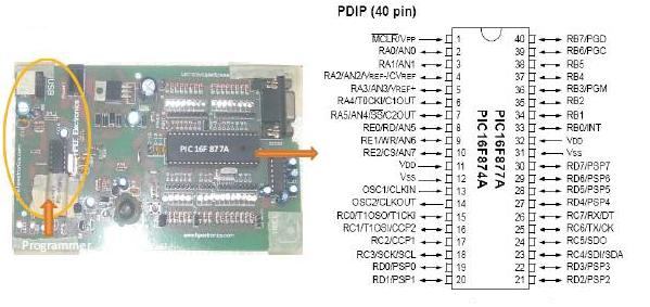
Figure 3(a). Development Board with Programmer and Pin Diagram of PIC16F877A
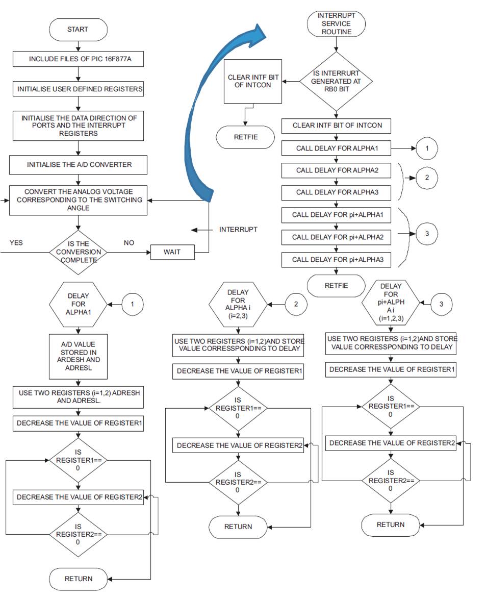
Figure 3(b) Flowchart for Pulse Generation.
The MPLAB IDE software simulator allows code development in a PC-hosted environment by simulating the PIC micro series microcontrollers on an instruction level. On any given instruction, the data areas can be examined or modified and stimuli can be applied from a file, or user-defined key press, to any of the pins. The execution can be performed in single step, execute until break, or trace mode.
Generating the hex code from MPLAB IDE software involves following steps.
PIC 16F877A is then simulated in PROTEUS 7 software that allows microcontroller based circuit simulation. Figure 4 shows the device library browser for selecting the components for simulation study. Figure 5(a) shows the proteus 7 simulation window and Figure 5(b) shows the simulated switching pulses in proteus 7. The positive half pulses are at a delay of α2=20o and α3=50o with respect to α1 which is the combination for minimum THD. Negative half pulses are at delay of 180o with respect to positive half pulse.
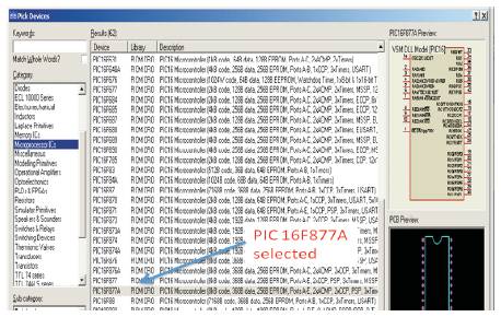
Figure 4. The Device Library Browser in PROTEUS 7
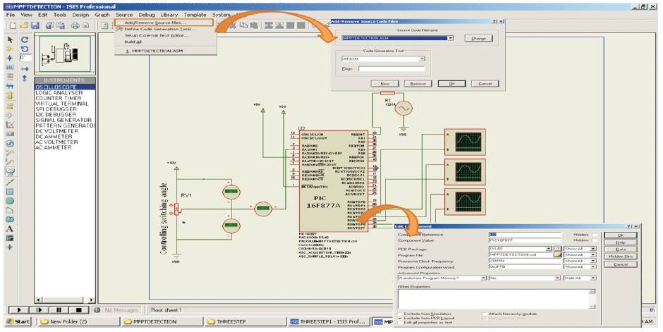
Figure 5(a) Simulation window of PROTEUS 7
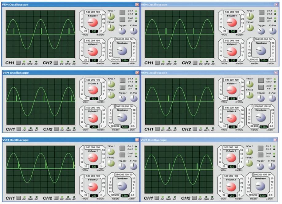
Figure 5. (b) Simulated pulses for Multilevel Inverter
Programming and using PIC 16F877A in PROTEUS 7 involves following steps.
The pickit2 programmer from microchip is used to burn the code into the chip. MOC3021 optoisolator is used to separate the power circuit with the triggering circuit. Figure 6 shows the positive half pulses obtained from the microcontroller. Figure 7 shows the grid voltage, line current and the instantaneous power. Figure 8 shows the harmonics in the line current.
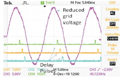
Figure 6. Positive Half Cycle Switching Pulses.
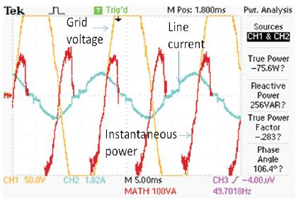
Figure 7. Grid Voltge, Line Current and Instantaneous Power.
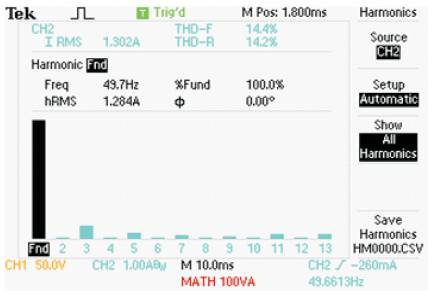
Figure 8. Harmonics in line Current in Figure 7
The average power flow is from the DC side to the grid. The harmonics in the line current in Figure 7 is shown in Figure 8. The THD has been reduced to 14.4% practically as can be seen from Figure 8. Thus a practical grid interactive multilevel circuit has been realised with switching control from microcontroller based circuit.