Figure 1. Vertical Axis Wind Turbine Construction
Wind energy is expected to contribute substantially to realize the sustainable development goals 2030 of the United Nations (UN). Substantial growth in global installed capacity of electric power generated from wind in the past decade has lead to corresponding upsurge in the research on Wind Energy Conversion Systems (WECS). This study endeavours to discuss various issues pertaining to the WECS. Fundamental terms of wind turbines, their types, application wise suitability, and the operational features are elaborated. Details regarding the blade designs and the aerodynamics are explained through necessary mathematical modeling. Also, a perspective is presented on various types of generators suitable for WECS along with specific attributes and shortcomings of each. The feasibility of multi-phase self excited induction generators for wind energy application is demonstrated through experimental results of six and nine phase variants.
Towards the end of 19 century, James Blyth (Price, 2005) and Charles F. Brush (Kaldellis and Zafirakis, 2011) demonstrated the feasibility of wind turbines for producing electricity. Subsequently, Marcellus and Joseph Jacobs of Montana, USA started commercial production of portable “wind machines” for low power applications rated up-to 1 kW. However, these earlier designs remained limited to few kW, off-grid, standalone units and were prevalent through the period of the Second World War. The Smith-Putnam turbine (Ajao and Mahamood, 2009) was the first MW rating wind turbine designed with a capacity of 1.25 MW introduced around 1949. Introduction of high rating turbines lead to the penetration of wind power into the realm of power grids and utility.
In the present context, the wind power is fast becoming a substantial source of electrical energy, especially in the post Fukushima Nuclear Disaster (Ten Hoeva and Jacobson, 2012) scenario. The unfortunate incident of Fukushima Daiichi plant compelled the nations all over the world to develop alternate sources of energy at much larger scale to replace nuclear power plants. Wind energy came forth as one of the viable options as the technical knowhow and necessary infrastructure was readily available in most of the countries.
Consolidation of wind energy across the world has caused manyfold increase in research and development activities on wind turbines. As a result, the modern wind turbine designs are under continuous recalibration for higher power yield, better control, and quality of generated power. Wind turbine aerodynamics (Bortolotti et al., 2016; Eboibi et al., 2016; Schubel and Crossley, 2012; Wang et al., 2016; Bai and Wang, 2016; Hansen, 2008) comes across as cumbersome web of intricate details involving application of complex theories of fluid flow. None the less, they are the pivots holding the key to turbine performance optimization.
Owing to its importance with regard to wind turbine per formance, various aspects of wind turbine aerodynamics are addressed by many useful studies. Hansen (2008) has elaborated the concepts associated with the wind turbine aerodynamics, performance optimization, wind simulation and the fatigue failures in detail. Branlard (2015) had investigated the wind turbine aerodynamics employing Vortex based methods. The conventional fluid dynamics based formulations solve for velocity and pressure to develop Conventional Fluid Dynamics (CFD) or the Blade Element Momentum (BEM) codes. But, the Vortex based analyses utilize localized curls of the fluid velocity fields and are becoming w i d e s p r e a d t o o l s f o r a n a l y z i n g w i n d t u r b i n e aerodynamics. Jeon and Lee (2014) have shown that a vortex based analysis could identify the Turbulent Wake State (TWS) (El-Askary et al., 2017; Xie and Archer, 2015) in floating offshore turbines as opposed to the BEM based methods.
Cold and icy terrain puts extra constraints on the wind turbine performance as it hampers the turbine aerodynamics severely. Many studies (Fakorede et al., 2016; Gantasala et al., 2016) render strategies for mitigating effects of icy atmosphere on the wind turbines and propose protective equipments for them. In Fakorede et al.’s (2016) study, various ice mitigation methods are reviewed to estimate the cost generation due to these measures. The effects of icing on mechanical and aerodynamic properties of a wind turbine are analyzed by Gantasala et al. (2016). The study shows that the blade with ice depositions experiences severe vibrations in the normal operating velocity range.
Small wind turbines are feasible option as standalone/grid connected wind-solar hybrid (Bingham et al., 2016) rooftop installations. In Tang et al.’s (2015) is study analyzed exclusively the design and development of small wind turbines. A direct approach is putforth for an efficient and economic blade design in small wind turbines by minimizing their rotor power co-efficient. The wind tunnels experiment approach is adopted by Seong et al. (2016) to extract automatic yawing information in small wind turbines for different angles of attack. The idea of the so called “kite wind generators” (Argatov and Shafranov, 2016) for the small scale wind energy systems has also come-up as a recent concept.
Apart from the wind turbine aerodynamics, the electrical energy outflow from a turbine is dependent to a great extent on the choice of electrical generator. It is crucial also since the wind turbines are invariably situated in far off and difficult terrains subjected to harsh winds and weather conditions. Electrical generator, therefore, in such a scenario may turn out to be the weakest link most prone to breakdowns (Alnasir and Kazerani, 2013; Lebsir et al., 2015; Khan and Khan, 2013). The electrical generators employed in wind turbines are primary classified on the basis of their ruggedness and the ability to offset the effects of variable wind speeds on generated power.
Different aspects of electrical generators for wind turbines are articulated in (Hansen et al., 2001; Serrano-González and Lacal-Arántegui, 2016; Murthy, 2016). The choice of generator stems from whether the generated power is to be utilized in isolated mode or injected in grid. From there on, other aspects such as the reactive power management, control circuitry, and other issues are devised.
The above mentioned studies on various aspects of wind energy conversion systems establish good understanding on their operating features. However, it is observed the some of the latest developments in the realm of wind energy are still to be pursued. Multi-phase generators could be most suitable for wind energy applications due their better ruggedness, fault tolerance, and compact size(Levi, 2016; Khan et al., 2017) compared to threephase. In this paper, a thorough review of various fundamental aspects of the wind turbine types, aerodynamics and blade design is carried out. Subsequently, multi-phase, capacitor excited induction generators of up-to nine-phase are discussed for wind energy application. The experimental results extracted on a multi-phase SEIG for six and nine-phase operation are reported in the paper to demonstrate their feasibility.
The idea of sustainable development lays great emphasis on two fundamental aspects associated with energy issues (Khan and Khan, 2013). Firstly, the older technologies must be replaced by new, energy efficient technologies enabling more judicious use of available e n e r g y r e s o u r c e s. S e c o n d l y, t h e c l e a n a n d environmental friendly methods must replace the conventional power generation technologies. Conventional power generation technologies, being predominantly fossil fuel intensive, are causing persistent and irreversible environmental damage. Apart from perilous to nature, the fossil fuel resources are fast receding and may not be available perpetually.
In an attempt to reverse the environmental damage and disseminate the sustainable growth concept, the UN laid down Sustainable Development Goals 2030 (UN, 2016). Out of the 17 well defined goals the “Affordable and Clean Energy” is up there at no. 7 emphasizing its importance. Wind has proved to be most beneficial of renewable energy sources harnessed thus far. The available data (GWEC, 2017) show that global installed capacity of the electric power generated from wind has grown at a CAGR of 15.3% during last five years, i.e., 2012- 2016. Thus, in realizing clean and affordable energy goal, the role of wind energy continues to be pivotal.
In practice, the wind turbines exist as Vertical-Axis Wind Turbines (VAWTs) or the Horizontal Axis Wind Turbines (HAWTs) though a number of variants derived from these fundamental types may still exist. The basic difference between the two designs is the placement of generator and the design of turbine blades.
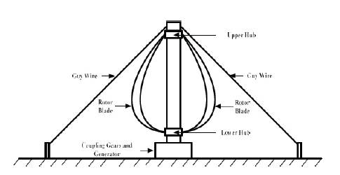
The vertical Axis Wind Turbines (VAWTs) have an inbuilt ability to augment wind coming from different directions without making any adjustment 'yawing'. The stability of VAWTs structure is enhanced due to the fact that generator and gear mechanism is placed on the ground. A schematic diagram of a VAWT showing different components is depicted in Figure 1 (Seyoum, 1977).
Figure 1. Vertical Axis Wind Turbine Construction
Due to vertical axis of rotor the VAWTs are more prone to suffer from the naturally varying torsional forces on the rotor caused by the variable wind speeds. Moreover, due to low tower height the power extraction capability of these turbines remain limited as the wind velocity is even slower towards the bottom of the structure. Because of these limitations the VAWTs are much more suited as small sized turbines for the applications where reduced noise and omni-directional capability of the turbine are required.
Inspite the substantial gains towards the wind generation installed capacity and the wind turbines in recent years, technological challenges still exist. The larger wind turbines, being capable of greater power capture, bring along economic advantages. Due to this, the operational size of wind turbines has increased almost exponentially over the last three decades. Wind turbines now a days are built in huge sizes with extremely flexible materials equipped with sophisticated controls for maximum extraction of power. Basic components of a horizontal axis wind turbine which dominates the modern wind turbine space are depicted in Figure 2.
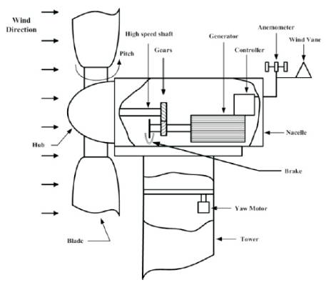
Figure 2. Main Components of a Wind Turbine
The HAWTs are driven predominantly by the lift effect of wind stream incident upon the rotor blades. The blades on the rotor may have an 'upwind' or 'downwind' orientation. While the number of rotor blades may also vary from one upwards. However, three blade topology is considered most optimum for power generation purpose and most of modern HAVTs are designed to accommodate triple rotor blades.
The generator and gear utilities are placed atop the tower in the turbine nacelle with the generator shaft connected to rotor via gear coupling. The placement of entire rotor atop a tall tower in HAWTs is highly beneficial as the rotor captures higher speeds from unhindered wind streams compared to VAWTs. The main components of a horizontal-axis wind turbine that are visible from the ground are its tower, nacelle, and rotor, as can be seen in Figure 3 (Seyoum, 1977). A number of control mechanisms can be implemented on HAVTs to extract maximum power from the available wind at a given velocity.
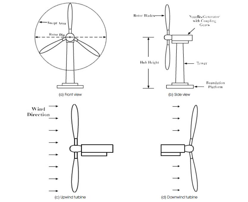
Figure 3. Horizontal Axis Wind Turbine
The fundamental aspects of a horizontal axis wind turbine dynamics are set forth as follows:
The kinetic energy of the system is defined as (Seyoum, 1977; Ragheb and Ragheb, 2011),
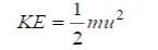
where, u is the velocity of air as it hits the turbine blades, m is mass.
Power (P) is obtained as :
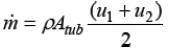
The mass flow rate m is given by the theory of fluid mechanics as,

where, ρ=air density (kg/m ),
A=area (m ), u = velocity (m/s
Equation (4) gives the total power contained by the wind and this entire power is not extracted in terms of turbine output power. This is due to the fact that P is the power produced at an unperturbed free flowing wind velocity u. But, in practice the wind velocity at the turbine will always be different than its free stream velocity. Moreover, as the turbine blades do not have uniform shape the wind velocity subjected to different portions of blade shall be different as well.
The flow rate of wind volume per second, i.e., (A*u) will remain constant because the amount of air entering wind turbine and leaving it remains same as there is no wind storage in the turbine. As a consequence to this the outgoing wind after crossing the wind turbine is at a lower pressure and the effective area covered by it increases (Seyoum, 2003; Ragheb and Ragheb, 2011).
The wind dynamics before and after crossing the turbine is depicted in Figure 4 (Seyoum, 1977; Ragheb and Ragheb, 2011). Here, the subscripts 1 and 2 represent the parameters before and after the convergence of wind on the turbine. Now, from Figure 4 the force (F) on the blades can be evaluated as the rate of changing momentum from 1 to 2.
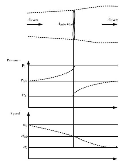
Fig 4. Wind Flow Diagram with Corresponding Pressures and Speeds
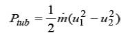
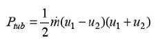
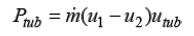
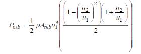
The power acquired by turbine from the wind stream, P tub can be written in terms of wind velocities before and after turbine from the fundamental expression of equation (2) as,
The power acquired by the turbine can alternatively be represented as,
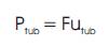
Replacing F in equation (8) from Eqn. (5), we have:
Equating the equations (7) and (9) results in the following equation,
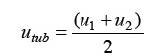
Thus, putting wind velocity at turbine u from equation tub (10) in equation (3) results in,
Now, the power extracted by the turbine from equation (6) becomes,
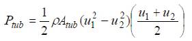
Rearranging above in terms of the turbine power developed with respect to the wind velocity u ,
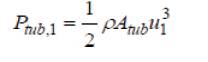
The turbine power with respect to wind velocity at point 1,
will yield the total wind power input to the turbine with a 1 surface area A . Incorporating these quantities in the tub fundamental equation (4), the turbine input power with respect to point 1 P can be written as,
From equations (13) and (14) the turbine power input and output may be correlated as,
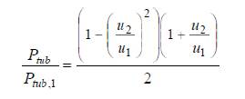
The quantity on the right side in above equation is known as the capacity factor C for a wind turbine and is a p dimensionless parameter. Thus incorporating the capacity factor a general power equation for wind turbine can be written as,
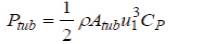
Thus C is performance indictor of a wind turbine as it p essentially gives the turbine efficiency. Now, defining a factor called the 'interference factor' m to correlate the upstream and downstream wind velocities, i.e. u and u , 1 2 such as (Seyoum, 2003; Ragheb and Ragheb, 2011),
From equations (15), (16), and (17) the capacity factor C p and the interference factor m can be correlated as,
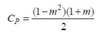
For all possible operating conditions m varies from 0 to 1. The maximum value of capacity factor can be obtained as,
The above solution yields two values for m given as -1 and 1/3, m=-1 implies that u =-u the physical interpretation of 2 1 such a scenario refers to opposite directions of wind in up and down streams which is not a probable scenario for all practical purposes. Thus, m=1/3 is the realistic scenario and it in terms of up and downstream wind velocities it occurs when u =3u . Thus, the maximum efficiency is 1 2 achieved by a wind turbine wind turbine when the wind converges towards turbine at a velocity 3 times of that at which it leaves in the downstream. Moreover, when m=1, u and u attain the same values which means there is no 1 2 perturbation in wind speeds yielding 0 capacity factor. Also, for m=0, the downstream wind speed u is also 0 1 which gives 50% efficiency that is C is 0.5.
As concluded above the maximum capacity factor is achieved at m=1/3, now the maximum value of capacity factor can be obtained by putting this value of m in equation (18) as follows,
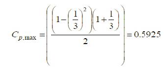

Equation (21) gives the maximum achievable efficiency by a wind turbine and is referred as the “Betz Limit” (Seyoum, 2003; Ragheb and Ragheb, 2011; Okulov and van Kuik, 2009). Practically this value is never achieved and maximum achievable limit remains less than 50%. Moreover, it varies directly with the size and speed of a
wind turbine. Variation of capacity factor with respect to the different values of interference factor is depicted in Figure 5 (Seyoum, 2003).
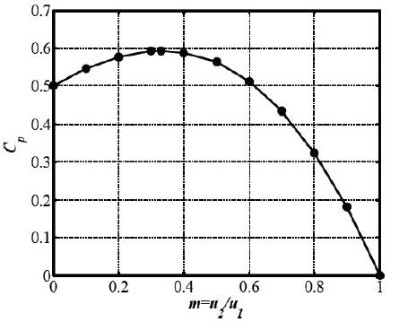
Figure 5. Variation of Capacity Factor for Different Values of m
The wind turbine blades utilize airfoils to produce mechanical power prompting the rotor motion. Various terminologies associated with the airfoils are depicted in Figure 6 (Earnest and Wizelius, 2011) along with their point of effect on an airfoil.
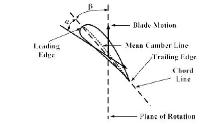
Fig 6. Various Terminologies Associated ure with a Wind Turbine Blade
The air moving over an airfoil exerts two forces on it in the form of lift and drag. The lift tends to act in a direction that is perpendicular to the air flow and the drag acts in the direction of airflow. The basic principle behind an aerofoil is described by Bernoulli's theorem. Basically this states that total pressure is equal to static pressure (due to the weight of air above) plus dynamic pressure (due to the motion of air).
The air blowing across an airfoil hits the blades at a certain angle of attack (α) due to which the air streams pass over and below the airfoil. The wind stream passing over the top of blade tends to move at a higher velocity compared to the wind stream along through the bottom part. This creates a pressure difference between the top and bottom portions of the airfoil. The greater wind speed in the upper portion creates an envelope of low pressure in the top vicinity of airfoil just; the reverse happens in the bottom portion. Thus, as a cumulative result to this the airfoil experiences a force perpendicular to the chord line and is called the 'lift'.
Besides the force experienced by the airfoil in the upward direction the movement of air tends to exert another force which acts in the same direction as that of wind movement. This is the 'drag' and actually represents a loss factor which has to be minimized as much as possible for optimum turbine performance. The mechanism of lift and drag is closely associated with angle of attack. As the angle of attack is increased the blade experiences greater lift, however there is a threshold for this increase o o (usually 14 to 15 ). If the angle of attack is increased beyond this threshold, the lift will decrease rapidly due to turbulence setting up in the upper blade region. The change in lift corresponding to increasing angles of attack is depicted in Figure 7 (Earnest and Wizelius, 2011). It can be observed that beyond a limit as shown by Figure 7(d), the air has detached almost entirely from the upper portion of the blade leading to maximum blade turbulence and rapidly decreasing lift.
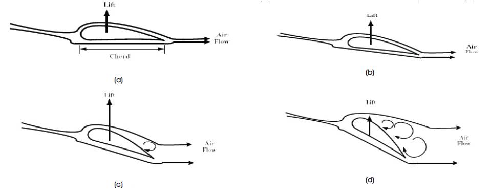
Figure 7. Changes in Lift Corresponding to Different Angle of Attacks
Such a condition can be extremely devastating, especially if it occurs in an air craft wing and is referred as 'stall'. Modern aircrafts are equipped with stall warning mechanisms to prevent such an event from taking place. In the modern wind turbines stall mechanism is effectively utilized to control the wind turbine speed to counter the effects of storms and high velocity winds on the generated power.
Because of the facts articulated above the HAVTs in particular have to adhere to specific wind directions incident upon the turbine blades. In general a HAVT must have the axis of its rotor aligned in the direction of wind all the time and due to this reason they are sometimes also referred as axial flow devices. The modern HAVTs are equipped with mechanisms to follow the changing wind orientations to optimize their performance. Unlike the HAVTs, the VAWTs are cross flow devices which means that the wind stream converges towards turbine blades across the axis of rotation. The blade rotation of a VAWTs traces a three dimensional surfaces rather than a circular span covered by HAVTs. Thus, the blades of VAWT are equipped with design provisions that exhibit better aerodynamic performance throughout a complete rotation at the different angles of attack they experience leading to high time averaged torque. The blades of a Darrieus type VAWT implement this by the lift and the Savonius type VAWTs generate the required torque through drag.
As discussed earlier the full power output will be extracted by a turbine when the wind stream is perpendicular to the plane of rotation. The pitch angle (β) is a static angle in the sense that it depends only on the direction of blade. On the other hand the angle of attack (α) is a dynamic angle depending both on the speed of wind as well as the speed of turbine blades. The blade speed at some distance d from the plane of rotation will be dω, where ω is the angular velocity of wind turbine blades (Ahmed, 2011).
If a blade has no twist then it will have variation in angle of attack as we move along the blade from the hub towards the tip because of the variation of dω with distance from the hub. The lift and drag will obviously exhibit their most optimum values when the angle of attack is maintained constant throughout the blade length. Thus, due to the same angle of attack from blade tip to the turbine hub the turbine gives out better efficiency compared to nontwisted blades. Thus, most of the modern wind turbines have twists which gradually increase from tip to hub. Contrary to this some designs also employ flat blade designs having no twists as they are cost effective and easy to manufacture. However, the compromise made on account of efficiency nearly cancels out the economy achieved in production. The concept of twisting the wind turbine blades is illustrated in Figure 8 (Ahmed, 2011).
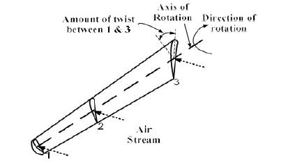
Figure 8. Basic Concept of Twisting Turbine Blades
Another important factor to ensure optimum performance of a wind turbine is the tip speed ratio. It may be defined as the ratio of tip speed (v ) of turbine blades to t the actual speed of wind (v ).
It is an important parameter in the sense that it ensures proper rotation of turbine blades. When the rotor rotates its blades all the blades rotate corresponding to the prevailing wind speed. If the rotor speed is too slow then all the wind will pass through the gaps in between the blades undisturbed. Conversely when the blades rotate at a very high speed they may create a solid shield effect allowing passage of very little air. Therefore the wind turbines have to be designed with optimum TSR.
When the blade of a turbine passes through an angular position it leaves behind turbulent air. Now, if the next blade arrives too quickly such that the left behind turbulence is still active, the blade will feel the flickering resulting in insufficient power extraction. On the other hand if the speed of blades is slowed down up-to a certain critical level so that enough passage of time is ensured to nullify the turbulence created by the blades ahead of them then the blades will move smoothly.
An optimum tip speed ratio depends upon the number of blades fitted on a turbine. The lesser number of blades implies that turbine has to rotate quicker to extract maximum power from the wind. A well designed three bladed turbine should have TSR of around 5.
Due to the unsteady and intermittent nature of wind source the wind turbines have to be equipped with necessary control mechanisms to make the power output as much linear as possible. A typical power curve of a 2 MW wind turbine is considered in Figure 9(Pao and Johnson, 2009; Stotsky et al., 2013) and is divided into three regions of wind speeds. The control systems for wind turbines are designed for these three regions identified as I, II, and III. When the wind speed is too low (less than 6 m/s in present case), the power available in the wind is too low. Under such a condition the power extracted by wind turbine is less than the losses therefore the generation is not done in this region, i.e. region I in the curve. Alternately, if the wind speed is too high typically above 12 m/s or so (region III) the generation limits have to be enforced. This is done to adhere to the safe electrical and mechanical working stresses on the wind energy conversion system. Also, if the wind speed exceeds too much and reaches up-to 'cut-off' speed of 22-25 m/s (Pao and Johnson, 2009) then the generation has to be stopped to protect the installation. The most preferable working point for a wind installation therefore exists in region II.
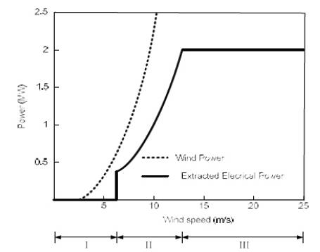
Figure 9. Power versus Wind Speed Curve
There are two important aspects associated with wind turbine control mechanism; Firstly there should be an overall monitoring regarding starting and stopping of wind turbines for cut-out wind speeds. Secondly, within the operating region-II and III, the control system ensures optimum quality and quantity of extracted power. The controllers employed in these regions utilize the generator, power electronics, yaw drive, pitch drive, and other actuators to achieve desired output power. Some of the control mechanisms implemented in modern wind turbine are discussed below.
The pitch control effectively limits the power whenever wind speeds go above rated value. Turbine blades are moved through pitching in such manner that the angle of attack is reduced to correspondingly decrease the lift on blades. Modern wind turbines are fitted with the sensors and actuators in the blade control systems. The sensors continuously sense the output power and send the signals to control system. If the power goes above reference limit the actuators process the sensor signals to activate pitching of blades through motors installed in the blade circuit. The blades are therefore moved in a direction away from the wind to reduce the turbine torque and bring the generated power down. The reverse process is activated as and when wind speed drops below rated limit. Wind turbines may be also of fixed pitch type, which refers to the fact that the blades are not able to rotate along their longitudinal axes. The fixed-pitch machines are simple to design and initially cost effective. However the reduced ability to control loads and change the torque means that they are becoming less feasible considering ever increasing power ratings and size of wind turbines.
Yaw mechanism is employed to keep the axis of turbine facing in the wind direction so as to maximize the power extracion. Conversely, yaw mechanism may also be employed to move the hub out of wind under high speed wind conditions. Either way because of the large inertia of nacelle high power rating wind turbines have to endure great mechanical stresses during yawing. Moreover, the degree of power control acheived through yawing is o limited as a tilt of about 10 results only in few percent change in power. In comparison to this same amount of tilt acheived in the blades through pitching results in up-to 50% change in power (Ahmed, 2011). Nevertheless, most of the modern wind turbines possess provisions for yawing through an intricate yaw control system consisting of motors, bearings, gears, etc.
The stall control makes use of stall charcteristcs of turbine blades to control ouput power within limits when the wind speed accedes above rated value. Under normal operating conditions as mentioned in the erlier discussions stalling of rotor blades should be avoided as it reduces the blade lift and increases the drag. However, such a characteristic becomes useful under heavy wind conditions to protect the rotor blades and generator circuit. There are two types of stall controls imlemented in the modern wind turbines knoown as the passive stall control and active stall control (Ahmed, 2011).
Variable-pitch turbines may allow all or part of their blades to rotate along the pitch axis. Moreover, wind turbines can be variable speed or fixed speed. Variable-speed turbines tend to operate closer to their maximum aerodynamic efficiency for a higher percentage of the time, but require electrical power processing so that the generated electricity can be fed into the electrical grid at the proper frequency. As generator and power electronics technologies improved and costs decreased, variable-speed turbines became more popular than constant speed turbines at the utility scale.
The generators equipped with a wind turbine are classified on the basis of their ability to absorb variations in input speed. Ideally a generator must provide the required power at constant frequency and voltage. However, the unsteady nature of wind presents maximum challenge for the generators as they endeavor to keep the generated output parameters constant. A brief classification of various power generators for wind turbine along with their attributes are given in Table 1.
Table 1. Classification of Power Generators Employed in WECS along with their Attributes
Wind Turbine Generators (WTGs) are classified chronologically from Type 1 to Type 4. The Type 1 WTGs are practically constant speed machines as their voltage and frequency are extremely sensitive to prime mover speeds. In the 80s and 90s these drives were widely deployed in wind turbines with stall control. To incorporate limited variable speed capability, the dual-speed wind turbines with two Type 1 generators for low and high speed operations were proposed (Hansen et al., 2001). Wind turbine manufacturer Vestas introduced Opti-slip (Li and Chen, 2008) concept for variable speed operation of WTGs with wound rotor induction generator. The WTG is referred as Type 2; Indian wind turbine manufacturer the Suzlon implements this technology in its Flexi-slip classicfleet wind turbines (Classic Fleet, 2016).
Modern wind turbines are more efficient than the traditional ones due to sophisticated controlling mechanisms. The Type 3 (Mansouri, 2016) and Type 4 (Tiara et al., 2016; Zaharia et al., 2016) WTGs offer wider control of output power with varying wind speeds resulting in optimized wind turbine performance. The Type 4 WTG is characterized by high rating of power electronics as it routs 100% power injected in the grid through converters and hence is an expensive option. Moreover, the processing of rare-earth (Neodymium) magnets used in PM drives is increasingly being criticized due to environmental and social hazards. As a result, the Type 3 WTGs or Doubly Fed Induction Generators (DFIGs) are fast becoming preferred drives for wind turbines. They are economical than Type 4 WTGs as the power handled by the converters in a DFIG is only 30% thereby having reduced rating and cost of associated power electronics.
When the type-1 generators are operated in standalone/off-grid mode they are equipped with the terminal capacitors as a source of reactive power. In such a configuration they are referred as the Self Excited Induction Generators (SEIGs) (Thomsen et al., 2014). Due to the proven attributes of multi-phase drives the multiphase SEIGs are being considered for standalone wind energy applications. The six-phase variant is especially in focus due to better practical suitability in terms of loading and excitation topologies (Khan, 2015; Khan and Khan, 2016). Typical configuration of six and nine-phase SEIGs along with their load voltage and current profiles are given in Figure 10 (a) and (b), respectively. Both the SEIG c o n f i g u r a t i o n s a r e o p e r a t e d i n s e l f -v o l t a g e compensating short shunt mode (Khan, 2015; Khan and Khan, 2016) for load voltage optimization.
Figure 10. Different Configurations of Multi-phase SEIGs (a) Six-phase Configuration (b) Nine-phase Configuration
The measured results depicted in Figure 11 show the load voltage and current response of six and nine-phase SEIGs supplying rated power of 2.2 kW at unity PF. Both machine variants are implemented on the same open stator winding, squirrel caged induction machine. Moreover, the optimum parameters, such as excitation and series capacitances for both systems have been selected experimentally. Due to more number of phases the inherent characteristics of SEIGs such as ruggedness and self protection are enhanced even further. Besides, the multi-phase SEIG of the identical rating as three-phase yields better THD profile, efficiency and the lower ratings of associated excitation and series capacitances (Khan, 2015, 2016). Thus, multi-phase SEIGs offer a viable alternate for standalone wind turbines for supplying power to off-grid areas and small villages.
Figure 11. Measured Output Parameters of Multi-phase SEIGs Supplying Rated Power of 2.2 kW at Unity PF (a) Load Voltage and Currents of Six-phase SEIG (b) Load Voltages and Currents of Nine-phase SEIG
A thorough review of various aspects pertaining to operation, control and aerodynamics of wind turbines is reported in this paper. Various types of wind turbines, their respective features and limitations are discussed. Mathematical modeling and the interpretation of different associated terms of horizontal axis wind turbines (HAVTs) are given a detailed treatment. Due to the higher power yield, control capability and the adaptability as well as the structural stability, the HAVTs are better suited for bulk power augmentation than the Vertical Axis Wind Turbines (VAWTs). None the less, the VAWTs still find favour in low power urban/rooftop applications due to their relatively noiseless and omni-direction operation. The multi-phase self excited induction generators are introduced as viable additions in the existing types of generators for wind turbines. The results obtained on six and nine phase self excited induction generators are included to demonstrate their practical viability.