(1)

There are different types of disturbance in power system like switching, transient, load variation, etc., which affects stability and efficiency of power system. These disturbances cause fluctuation at low frequency which are unacceptable, as they decrease the power transfer capability in transmission line and unstable mechanical shaft load. In order to compress low frequency oscillation, a common solution is the use of Power System Stabilizer (PSS). This paper provides Ant Colony Optimization (ACO) algorithm based approach for robust and optimal design of power system stabilizer proposed for the single machine infinite bus hydro governor turbine generator. The proposed design of the controller is formulated as a parameter optimization problem based eigenvalues, damping ratio, and time domain analysis. The simulation results by proposed design approaches when compared with conventional PSS show better results.
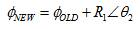
In modern electrical power system, stability acts as an important criteria for performance analysis of network. Power System Stability is ability to regain synchronism on occurrence of small and large disturbances. Stability can be classified in mainly two parts [5]: Transient stability and Small signal stability. Automatic Voltage Regulator (AVR) is used for improving transient stability and controls the oscillation of frequency ranging from 0.1 to 2 Hz. AVR and generator field dynamics introduces a phase lag so that resulting torque is out of phase with both rotor angle and speed deviation. Positive synchronizing torque and negative damping torque often result in cancelling the small inherent positive damping torque available, leading to instability. This type of regulator is designed for specific operating condition, hence limit the output results. Different type of controllers like Fuzzy logic controller, a proportional, Derivative and Integral (PID), and Power System Stabilizer (PSS) are used as solution to these problems. The different controller structures are always the field of interest for researchers. Power System Stabilizer type controller is used for improving damping of electrical power systems. This is generally accepted in the industries for various applications. This paper investigates the stability performance using tuning of different variables of Power System Stabilizer through Ant Colony Optimization technique. In this paper, an optimum tuned PSS controller is designed and performance of this controller is investigated using ITAE performance index. So, in this paper Conventional Power System Stabilizer (CPSS) and Ant Colony Optimization based PSS controller models are evaluated for single machine infinite bus with hydro governor turbine generator systems and performance is compared with Conventional Power System Stabilizer (CPSS) [7, 13].
By using biological inspired Ant Colony Optimization Algorithms, it is found that the closed loop system has very fast rise time, settling time, and reduces maximum overshoot to sustain the system stability under different conditions. From the transient response, it is observed that Ant Colony Optimization Algorithms gives fast response.
In this work, the authors utilize the Ant colony optimization algorithm for computing the optimal PSS controller parameters in the power system network. To complete the tuning process, objective function should be defined and they give satisfactory results.
1.1 Case Configuration
The test case consists of hydel power system comprising a single machine connected to infinite bus bar. A nonlinear differential equation can be represented by the following as [10],
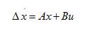
where x and u are vectors representing the state variables and the input variables vector, respectively. In the design of Power System Stabilizers, the linearized incremental models around an equilibrium point are usually employed [1]. The general expression of a power system can be represented in terms of state equations as,
Moreover, a brief introduction of the considered systems is given in the next sections.
In operation of power system network synchronous machine is essential. A synchronous generator which is connected to an infinite bus is shown in Figure 1.

Figure 1. Single Line Diagram of SMIB System
The inter connection of transmission lines to generator, turbine, AVR, excitation system, and PSS controller is shown in Figure 2 [1, 3, 4].
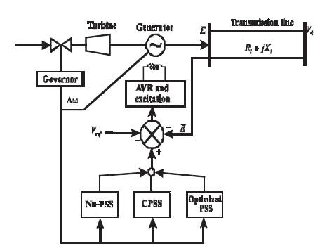
Figure 2. Connection Diagram of SMIB with PSS
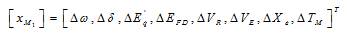
The linearized model of Single Machine Infinite Bus power system (SMIB) known as Heffron Phillips block diagram with PSS [6] is shown in Figure 3.
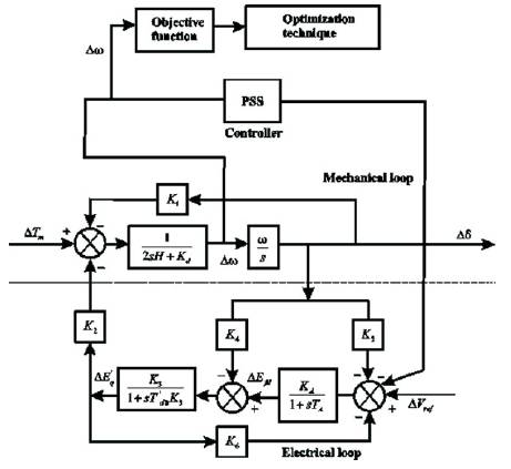
Figure 3. Representation of Heffron –Philip Model with PSS and Tuning Scheme using ACO SMIB Power System Model
In stability analysis of single machine systems, the input power (mechanical, i.e. P ) is generally assumed as a non m variant quantity (constant). But in this work, mechanical power input is considered in terms of hydel governor and turbine model along with the model of the hydel generator for modeling and simulation of the system
In this work, hydel generator is equipped with hydel governor and turbine. The transient droop compensation block is not included in the hydel governor model. The IEEE Type 1 excitation (rotating exciter type) is taken in this model.
Hydel governor and turbine model is shown in Figure 4, where T and T are the time constants of hydel governor and turbine, respectively. The output obtained from the model of the hydel governor turbine is fed as input to the Single Machine Infinite Bus (Heffron-Phillips generator) model.
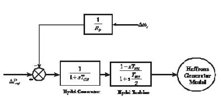
Figure 4. Block Diagram of Hydel Governor Turbine with Heffron-Phillips Model
For this model, the generator is connected with excitation system (IEEE Type 1) shown in Figure 5.
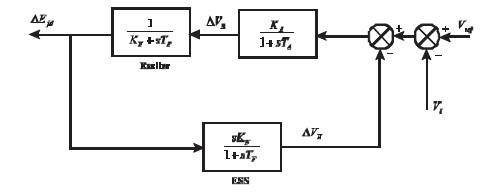
Figure 5. Block Diagram of Excitation System Model
This excitation model represents rotating exciter configuration and it consists of exciter, amplifier, and Excitation System Stabilizer (ESS).The ESS is used to increase the stable region of operation of excitation system K , K , K and T , T , T represent the gain and time A E F A E F constant of the amplifier, exciter, and ESS, respectively.
The state space equation of hydel model is given by,
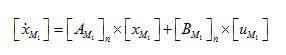
where, n= Number of hydel generators, here n=1.
A and B = State matrix and input matrix of hydel model, M1 M1 respectively. and A = State variable vector of hydel M1 model.
Equation (4) indicates the state variables selected for this model for open loop analysis.
Similarly equation (5) indicate the state variables for closed loop analysis.

Here, (5), ,and represent the state variables involved in the closed loop PSS model.
The complete model of the hydel system is shown in Figure 6 which consists of generator, governor turbine, and PSS excluding transient droop compensation block.
Figure 6. Complete Block Diagram of Hydel Power System Model with PSS
The block diagram of power system stabilizer [14] as shown in Figure 7 consists of three blocks, namely gain, washout, and identical phase compensation block (the cascade connection of blocks viz; lag and lead compensation). The gain (K ) and the time constants (T , S 1 T , T , & T ) of phase compensation block are tuned 2 3 4 effectively, so that the damping controller provides the required damping torque to damp the power oscillations. The deviation in the rotor speed Dw acts as input to the r controller and output obtained is the damping control signal (Dv ). This output acts as input to the feedback loop consisting of generator - excitation system as shown in Figure 8.
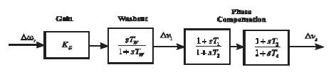
Figure 7. Power System Stabilizer Controller Model
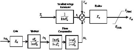
Figure 8. Power System Stabilizer with Excitation System
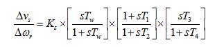
The PSS controller is governed by the transfer function given by,
The primary goal of formulated objective function is to minimize the error signal to improve the system stability, i.e. difference between input and desired input. Error performance criteria are being applied for reducing the error. In this paper, authors use Integral Time Absolute Error (ITAE) criteria for reducing the error 9, [11]. The expression of ITAE is described as follows,
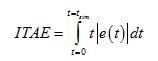
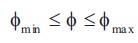
Subjected to,
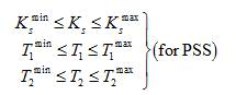
In this work, the time constants involved in the identical phase compensation block of the damping controller are considered as per the criteria. The values of controller parameters K , T , and T in closed loop modeling of the S 1 2 system determine the magnitude of damping given to the system considered. The following are the controller gain and time constant limits (minimum and maximum values) taken for algorithm implementation: for the gain Min Max Min Max (K = 1 and K = 70), time constant (T = 0.1 and T S S 1 1 Min Max = 2 s) and (T =0.1 and T = 2 s) (IEEE Standards, 2005). 2 2 The above mentioned objective functions with controller parameter constraints has been implemented in hydel power system to compute the optimized tuned controller parameters, essential for improving stability of the power system models considered.
1.4 Eigen Value Analysis
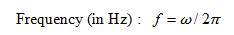
In power system, stability of the linearized system is determined by the eigenvalues of the state space matrix. A real eigenvalue, or a pair of complex eigenvalues, is usually referred to as a mode [2, 12]. For a complex mode l =s ± jw, two quantities are of main interest.

The system is unstable if x is negative. To ensure the acceptable performance, a damping margin in the range of 3%-5% is normally required.
Marco Dorigo proposed this algorithm in 1992[15]. The Ant Colony Optimization algorithm is used to optimize the gains and time constant of PSS and the values are applied into the controller of the electrical power system. The objective of the proposed algorithm is to optimize the parameters determining the performance of the PSS controller for the given power system network. The flow chart of Ant colony optimization is shown in Figure 9.

Figure 9. Flow-chart to Explain Steps for ACO Algorithm
The algorithm for Ant colony optimization is given as a step by step procedure.
Step 1: Initialize ants
With streamline distribution technique begin the initiation of valid and accurate solutions for the PSS parameters. Also put up the pheromone trail along with heuristic value. Generally ants are denoted as a , a ,.....a ....,a , where n 1 2 k n represent the total number of ants in a colony. All the values together constitute the population of the ant colony.
Step 2: Determination of objective function value F(f)
With minimum error focus on computing the heuristic value linked up on the objective function, with th placing A Ant over the node. The function to be minimized represents each ant in the colony is determined by equation (11).
Step 3: Determination of pheromone value at different ant locations
The pheromone content at each ant location is th determined: the pheromone value at the j location is found by equation (12).
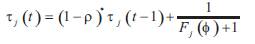
where r is known as evaporation constant. Range of r is taken between 0 and 1, with permitting the forgetting part over the bed choices.
Step 4: Determination of movement probability
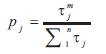
The levels of the pheromone at a particular location determine the trajectory of motion which decides the movement probability p . Movement probability is j calculated by using (13).
Step 5: Dispatching of ants
When p ³ p is satisfied, it depicts the presence of the ant in j t promising region of the available solution space. Thus the new position of the ant is given by equation (14).

Taking up the optimization parameters, reflect the optimum value
Step 6: When p ³ p is not satisfied, it depicts that the ant is j t present in less favorable region of the available solution space. Thus the new position of the ant is given by equation (15).
With the solution calculated to optimum level update the pheromone value.
Step 7: With continuous loop, from earlier step 2 go on for iterative value until maximum iterations are achieved.
In SMIB hydel power system simulation, a 247.5 MVA, 16.5 KV, 180 rev/min hydel generator are considered as the test system model. The system data used for simulation of the various model configurations are given in Appendix.
In this analysis, performance of hydel power system stability is analyzed, whenever the model parameters and operating conditions are varied with two different conditions. For modern power systems, this analysis is highly effective for stability analysis of the system considered.
The studies are carried out with variations in operating conditions, gains and time constants of various components involved in the model, system inertia, changes in load disturbance (DP ), etc. Using MATLAB tool, d the open loop single machine hydel power system models are simulated for various operating conditions with load change disturbances.
The eigenvalues and damping ratios for weakly damped open loop system in two different operating conditions are listed in Table 1.
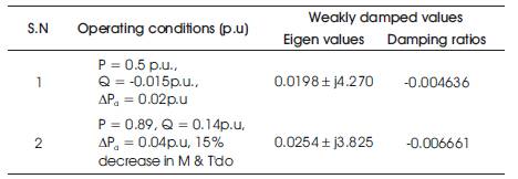
Table 1. Open Loop Damping Ratios and Eigen Values
The obtained values of open loop system indicate that the hydel power system is in un-stable condition, as the damping ratios are negative and eigenvalues (weakly damped) are located at right side of s plane.
The electromechanical oscillations are analyzed in terms of speed and power angle deviations. Figure 10 and Figure 11 represent the response of deviation in speed and deviation, respectively in power angle of single machine hydel power system for first condition. The deviation of speed and power angle is gradually showing an increase in magnitude, thus making the system more unstable. Thus, the system requires a controller in order to enhance stability.
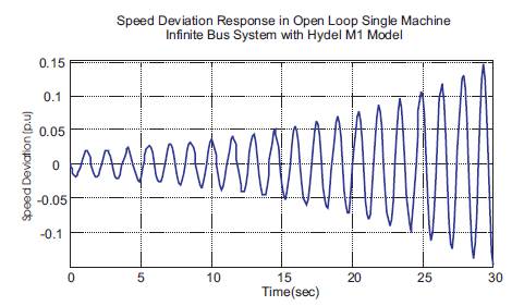
Figure 10. Speed Deviation Response of Single Machine Hydel Power Case-1
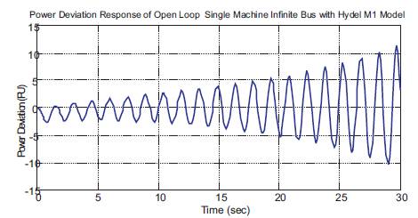
Figure 11. Response of Power Deviation in Single Machine Hydel Power System for Case-1
3.1.1 Stability Analysis
The stability analysis of the system model under consideration with controllers involved in this work is performed based on two main categories.
Analysis of eigenvalue and damping ratio for weakly damped closed loop system. •
•Analysis of time domain response for deviation in rotor speed and power angle
In this work, two types of damping controllers, namely Conventional PSS and Ant Colony optimized PSS have been implemented in the hydel system models considered.
The parameters of Ant Colony Optimization listed in Table 2 are taken for implementation of Power System Stabilizer controllers designed for hydel power system.
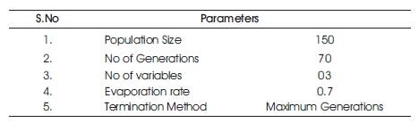
Table 2. Ant Colony Optimization Parameters Implemented for Controller Design
For better stability enhancement, optimize tuned controller parameters, namely K , T , and T are to be S 1 2 computed using Ant Colony optimization based controller design implementation. The computed optimal controller parameters of the system are used in the closed loop state matrices of the hydel models to calculate the stable eigenvalues and damping ratios of the system.
Table 3 provides the eigenvalues, damping ratio for weakly damped closed loop system and controller parameter of the system is calculated for two different operating conditions using the computed optimal damping controller parameters.
When the electrical power systems are subjected to electromechanical oscillations, damping ratio if greater then 0.05 lead to stable system, so in this work the desired benchmark for the damping ratio is considered as ξT = 0.06 for attaining stability [8].
In first condition, P=0.5 p.u. Q=-0.015 p.u., and DP =0.02 d p.u in Table 3, the controller parameters (K =14.253, S T =0.15, T =0.098) are substituted in Appendix along with 1 2 values of other parameters to calculate the eigenvalues and damping ratio for Conventional PSS. For the same operating condition, the optimized controller parameters (K =22.823, T =0.0937, T =0.694) for ACO-PSS, are S 1 2 substituted in Appendix along with values of other parameters to calculate the damping ratio and eigenvalues.
The eigenvalues are placed in left hand side of s-plane for the system stability. In first case, the maximum value of real part in open loop analysis (0.0198, as per Table 1) is minimized to (- 0.3683, -0.8785 as in Table 3), CPSS and ACOPSS controllers implementation in the system. The eigen values for ACOPSS are better in comparison with Conventional PSS in improving the stability of hydel power system.
The damping ratios are calculated using this eigenvalues for two different cases, as listed in Table 3. The PSS controller proposed in this work results in better damping of hydel system where the values of the damping ratio is always greater from threshold level in all operating conditions.
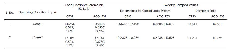
Table 3. Eigenvalues, Damping Ratio, and Controller Parameters for Hydel System Models
For the second case, the minimum value of damping ratio in open loop analysis (-0.00408, Table 1) is maximized to (0.0511 and 0.0971 as in Table 3).
The Ant Colony Optimization based stabilizer (ACOPSS) provides better damping, with damping ratio more then the threshold limit for two different conditions involved in Table 3.
In this part, analysis is carried out to minimize the error using ITAE criteria involved in speed and power angle deviations (as discussed in objective function). This is analyzed in terms of minimizing the settling time and overshoots of the speed and power deviation responses. The response of deviations in speed and power angle is obtained by implementing the three damping controllers parameters (K , T and T ) in the system for P=0.5, Q=- S 1 2 0.105, DP =0.02 p.u condition is shown in Figure 12 and d Figure 13. These responses show that the Ant Colony Optimization PSS provides improved damping to minimize oscillations when compared with the performance of conventional PSS controllers. Fitness function versus iteration curve is shown in Figure 14.
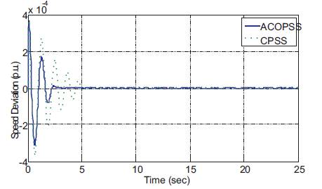
Figure 12. Responses of Speed Deviation in Hydel Power System for Case -1
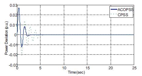
Figure 13. Responses of Power Angle Deviation in Hydel Power System for Case-1
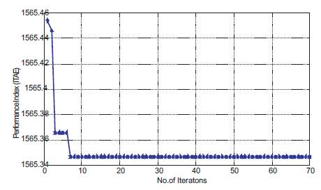
Figure 14. Performance Index vs. Iteration Curve for First Condition
In Table 4, the maximum deviation overshoot obtained for -4 Conventional PSS is 3.76´10 p.u, and for ACOPSS, overshoot obtained is only 1.84´10 p.u. Also in power angle maximum overshoots obtained for Conventional PSS is 0.028 p.u, and it is only 0.016 p.u for ACOPSS, so the oscillations settle (at 5% of the steady state value) at 6.210 s for Conventional PSS, and it is only around 2.38 s for ACOPSS, as in Figure 15.

Figure 15. Responses of Speed Deviation in Hydel Power System for Case-2
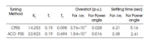
Table 4. Over Shoot and Settling Time with Different Tuning Method for Case - 1
These inferences clearly satisfy the objective function formulated to achieve stability. It is clear from above table, the Ant colony optimization based controller reduces the deviations in overshoots to a much better extent and also the time taken by deviations to settle decreases
Similarly, responses of speed deviation and power angle deviation in second operating conditions are presented in Figure 15 and Figure 16 respectively. Fitness function versus iteration curve for this condition is shown in Figure 17.
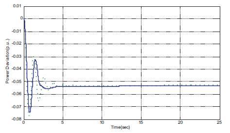
Figure 16. Responses of Power Angle Deviation in Hydel Power System for Case-2
In Table 5, the maximum deviation overshoot obtained for -4 Conventional PSS is 3.980x10 p.u, and for ACOPSS, -4 overshoot obtained is only 2.460x10 p.u. Also in power angle maximum overshoots obtained for Conventional PSS is 0.078 p.u, and it is only 0.078 p.u for ACOPSS, so the oscillations settle (at 5% of the steady state value) at 7.28 s for Conventional PSS, and it is only around 3.27s for ACOPSS, as in Figure 16.
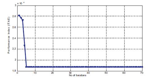
Figure 17. Performance Index vs. Iteration Curve for Second Condition
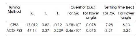
Table 5. Maximum OverShoot and Settling Time with Different Tuning Methods for Case-2
All these simulated responses reveal that the proposed Bio-inspired controllers are more robust in damping the oscillations better than the conventional controller, thus improving the stability of hydel power system.
The proposed method for stability improvement has been tested on two cases of hydel power system which consists of single machine connected to an infinite bus. All the results discussed in this paper approve that Ant Colony algorithm in hydel power system could optimize the parameter of PSS and stability is greatly enhanced by the imp l eme n t a t i o n o f d amp i n g c o n t r o l l e r s. T h e Conventional PSS Controller enhances the performance of the hydel power system. But, it does not give optimal solution required for stability. Since the gain and time constants are found by mathematical formulae, the computed solution will not be the best solution for wide ranges of different operating conditions. The proposed Bio-inspired controllers provide better damping to the s y s t em a n d ma ke t h e s y s t em mo r e s t a b l e. Comparatively, the Ant Colony Optimization based Controllers provide the best possible positive damping to the system than the Conventional Controllers for different operating conditions considered in this work.
Recommendation of the study is as follows,
Generator Data: 247.5 MVA, 16.5 KV, 180 rev/min, M=10, T =7.76 s, D=0, X =0.98, X' =0.2, X =0.6
Excitation System Data : K =200, K =0.03, T =0.049 s, A F A T =0.025, T =1, K =0.2,
Turbine and Governor Data: T =0.3, T =6.5, T =1.5, GH R W R =0.05, R =0.5.