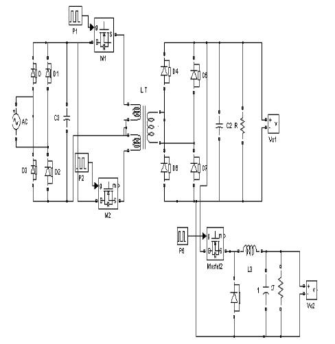
Figure 1. Push Pull Resonant Converter
This paper deals with simulation of open loop and closed loop controlled multiple output AC to DC converter using Matlab simulink. The multiple outputs AC to DC converter are capable of giving 12V and 5V DC. This conversion has advantages like reduced transformer size and reduced filter size. The results of closed loop system are presented.
A common case is information loss caused by the utility shutdown in PCs. There are many industrial applications in which a mains failure can cause serious damage, not only to the equipment, but also to the process involved. Nowadays, new company buildings usually have an uninterruptible power system (UPS) that feeds the equipment of the whole building. However, in many other cases, each individual user has to connect a personal UPS to the computer in order to avoid an unexpected shutdown. There are many commercial type of products but, in general, all of them are AC UPSs and their output voltage is an AC voltage (sinusoidal, square, trapezoidal, etc],. However, the problem can be solved in other ways, i.e., by supplying the DC output voltage of the power supply directly from the battery (dc UPS) [5-10]. This approach is also feasible, especially if there is only one DC output. Moreover, if the nominal input also be duplicated voltage is similar to the battery voltage. The solution can be simple because the same converter can be used and only some kind of switch should be implemented in order to feed the converter from the mains or from the battery. On the other hand, a power conversion should be done if the battery voltage is different from the nominal input voltage, and the usual way is to use another DC–DC converter to transform the battery voltage into one similar to the nominal input voltage. Of course, the other option is to obtain the output voltage directly from this auxiliary converter.
However, if the power supply has multiple outputs [1-2] (as in a PC power supply) all of them are completely regulated, the solution is not so simple because the output voltages cannot be directly obtained from the battery unless the whole power stage is duplicated, that is, it has two completely different converters one is operating from the mains and another one operating from the battery, and both of them obtaining all the output voltages. Obviously, the size and cost of the system will also be duplicated.
Moreover, from the industrial point of view, it could be interesting to design a modular power supply which could be based for other types of applications and not only for a PC, which is for a very specific use. There are many other industrial multi output power supplies but the voltage values can be very different. Therefore, the manufacturer could use the same product for different customers if the output voltages and power ratings can have some adjustment capability.
The topology used in this paper is based on the idea of a multi input converter one input being the AC mains and the other input being the battery. In previous cases [7], [8], this concept was used with the flyback converter and the forward converter and each individual input had a specific control circuit with a specific pulse width modulation (PWM) IC. The topology presented here is based on a half-bridge converter and the battery input is integrated with the secondary winding. Thus, there is no additional specific winding in the transformer to connect the battery. Furthermore, there is only one control circuit for both inputs and only one PWM IC is used. A simple logic circuit sends the PWM pulses to one input or the other, depending on the voltage of the AC mains. If the mains fail, logic circuit will send the PWM pulses to the battery input instead of the AC input.
The objective is to design a 200-W power supply with multiple outputs that can operate either from the ac mains or from a 12-V battery. This voltage value was selected for two main reasons: cost and safety. It is obvious that, from the point of view of the topology, it would be much easier to make the power supply operate from a high voltage battery than from allow voltage one [3]. In fact, if the battery voltage is high enough (around the peak value of the ac input voltage), we could use the same converter but fed from a dc voltage.
However, from the safety and the reliability point of view, this option is highly inadvisable. Furthermore, high voltage batteries are much more expensive than low voltage batteries. Therefore, the selected voltage is 12 V, mainly due to the extremely low cost of this type of battery. On the other hand, this voltage value complicates the implementation of the UPS considerably because the power supply should operate from two very different input voltages. The mains ac voltage (190–265 V rms) and the 12-V battery dc voltage. The option of using a very wide input voltage range converter has not even been considered because of the performance of these converters [12-15].
Another important issue in this design is the modularity of the system. Although the objective is to compile with the ATX specifications, especially as far as size is concerned, it would be very interesting if we could select the value of the output voltage inorder to use the same power supply for different applications. For this reason, the main output of the AC/DC converter is a 12-V output that can drive the total rated power (200 W).The other outputs are then post regulated from this main one (in our case, the main DC/DC converter is a half-bridge converter) by means of buck converters. Thus, any voltage combination can be obtained by selecting the appropriate post regulators. Bearing in mind that a PC needs quiet low voltages to operate (5 and 3.3 V), the buck converter designed for this purpose is synchronous buck converter in order to improve the efficiency as much as possible. Although the use of a synchronous MOSFET is more expensive than the use of a conventional Schottky diode, the efficiency improvement reduces the cost of the heat sink needed and enlarges the autonomy of the UPS. Moreover, as the input voltage of the buck converter is not too high (12 V), the cost of the control and drive circuit can be further reduced. A special effort was made to design as simple, cost effective, and discrete drive circuit avoiding the use of either pulse transformers or expensive commercial drivers. It should be mentioned that the buck output voltage is trimmable from around 9–3 V. Two of these post regulators can be incorporated into the main board therefore, the power supply can have up to two different power rails-two of them with a selectable output voltage.
It should also be mentioned that two more outputs (−12 and−5 V) are also obtained from the main converter. In this case, due to their low power ratings, the −12-V output is obtained from the main transformer and regulated by means of cross-methods coupling both output inductors in the same core. The 5-V output is obtained from the 12-V output by means of a linear regulator connected in cascade.
The first option is to put the battery on the primary winding and to use a converter to charge the bulk capacitor directly from the battery. Thus, the main DC/DC converter will always see a similar dc input voltage. With this option, the voltage difference between the input and the output will be quite large (10–14 to 300–400 V), and it will be necessary to design septic converter (control system, specific transformer, etc.,) for this purpose. It should be noted that this converter would only operate for a few minutes in case of a mains failure; therefore, its cost should be minimized, although this converter would have to drive the total rated power (200 W). In this case, the best option would probably be a flyback converter because of its simplicity, although the size of the transformer would be quite large.
Another option is to put the battery on the secondary winding. At first sight, it seems easier to obtain a tightly regulated 12-V output from a similar input voltage. However, this is not obvious at all because the battery voltage can change from around 10–13.6 V and as a consequence, the converter needed should be able to step-up and step-down the output voltage depending on the input voltage. The solution may be to use a buck–boost converter, but this means building whole converter semiconductors, capacitors, one inductor, and a control circuit.
Better option might be to make good use of the main transformer and try to drive the power from the battery to the 12-V output by means of an auxiliary winding (Triport solution) [5-8]. We should remember that the main converter is a half bridge; therefore, if the same transformer is used, the winding should be driven in a similar way (a fly back converter could not be connected to this winding because the transformer would saturate). In our case, the best option seems to be to place the auxiliary winding on the secondary winding. As the values of the input and output voltages are very close, the best solution is to use a push–pull converter (Figure 1) because both switches are connected to ground and the transformer is driven symmetrically as in the case of a halfbridge converter. Moreover, the push–pull winding can be integrated in the half-bridge secondary winding.
Figure 1. Push Pull Resonant Converter
The input dc voltage ranges from 265 √2 = 375 Vdc to 190 √ 2 − 20% = 220 Vdc (−20% represents the ripple across the bulk capacitor). If the maximum duty cycle is set around 0.42 in order to have some margin for dynamic regulation purposes at low line conditions, the main transformer turn ratio should be n=8.Thus the Maximum duty cycle is 0.43, the minimum duty cycle is 0.25, and the nominal duty cycle is around 0.32. [11]. Now, if a mains failure occurs, the push–pull will start operating. If windings, this converter is designed to operate with the same duty cycle range as the half-bridge converter; the transition between both modes of operation will be very fast because the regulator will not have to accommodate its voltage even is too much.
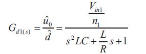
In a half-bridge converter, the relationship between the input and the output voltage is
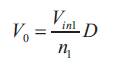
Where V in1 is the input voltage of the converter and n1 is the transformer turns ratio between the half-bridge primary winding and the secondary winding.
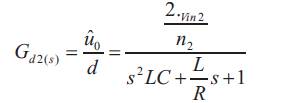
In a push–pull converter, the relationship between the input and the output voltage is
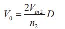
Where V in2 is the input voltage of the converter and n2 is the turns ratio between the push–pull primary winding and the secondary winding.
If the same output voltage is to be obtained with the same duty cycle, the following expression can be obtained from (1) and (2)
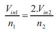
Let us assume that the average voltage across the bulk capacitor is 300 V in nominal conditions, the battery voltage is 12 V, and turns ratio of the half-bridge converter is n = 8. From equ.3 necessary turns ratio for the push–pull converter is n2 = 0.6 and the closest feasible turns ratio is n2= 0.5. Thus, the winding structure of the transformer will be: primary winding 16 turns, each half-bridge secondary winding two turns, and for each push–pull primary winding one turn Figure 2(a), (b) shows the half-bridge converter with the UPS based on a push-pull converter
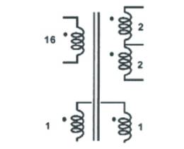
Figure 2. (a) Transformer windings and their number of turns for the basic solution.
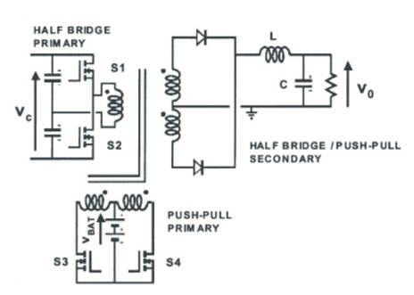
Figure 2. (b) Half-bridge converter with a push–pull coupled on the same transformer.
Obviously, due to the difference between both input voltage ranges (375/220 = 1.7 on the mains and 13.6/10 = 1.36 on battery), it is not possible to optimize this feature for the whole range but just for nominal conditions.
Furthermore, the small-signal transfer function of both converters is very similar because in both cases, the dynamic behavior is dominated by the output LC filter. The transfer function of the half-bridge converter is given as
and the transfer function of the push–pull converter is given as
Where L is the output filter inductor, C is the output filter capacitor, v0 is a small signal perturbation of the output voltage, and this is a small signal perturbation of the duty cycle.
As the output filter is the same and the turns ratios of both converters have been designed in such a way that the ratio equ.3 is similar, both transfer functions will be practically identical. Thus, the same voltage regulator can be used if the converter is powered either by the halfbridge or by the push–pull.
However, this structure can be rearranged in order to integrate the push–pull windings into the half-bridge secondary. As we know, the voltage waveforms on the trans former are similar in a half-bridge and in a push–pull. The secondary winding of the half-bridge transformer can then be also used as a push–pull primary winding. Thus, as the battery is placed in the secondary of the power supply and no isolation is needed, the transformer can be used as an autotransformer and share the same winding for the primary of the push–pull converter.
Instead of winding each half-bridge secondar y altogether (2 turns), each turn was wound separately in order to have the point available on a pin of the coil former (points D and E), as shown in Figure 2(c).
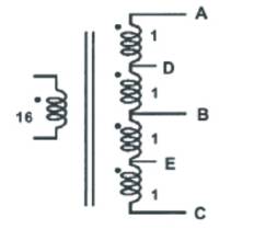
Figure 2. (c) Rearrangement of the windings to eliminate the specific push–pull windings.
Thus, in order to implement the push–pull converter, the battery only needs to be connected to the center point of the whole half-bridge secondary winding (point B) and each MOSFET to the middle point of each leg (points D and E). This way, each push–pull primary has one turn and the secondary has two turns as in the previous arrangement (the diodes of the secondary are connected to points A and B) Figure 2(c),(d). As we can see, one turn is used both for the primary and the secondary.
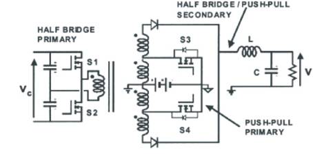
Figure 2 (d) .Half-bridge converter with a push–pull integrated on the same secondary
A very important feature of this system is that the transition between the normal operation mode and the mode can be done really fast. As mentioned earlier, the small-signal transfers functions of both the main half-bridge converter and the push–pull converter is quite similar. Thus, the same PWM controller and the same voltage regulator circuit can be used for both converters to drive the pulses from one converter to the other. Therefore, only one PWM integrated circuit is used and no control or protection circuitry is duplicated. The only extra components are the MOSFETs of the push–pull converter and no additional windings and no additional circuitry are needed.
When a mains failure occurs, the input voltage detector circuit activates a logic circuit and diverts the gate pulses from the half-bridge to the push–pull. The transition between both modes of operation can be done in one high frequency switching cycle.
As a consequence, the capacitor placed at the 12-V output should not be over dimensioned because it can no longer store any additional energy for the transition time. There will not be any switching cycle with no energy flow from the input to the output. In fact, the ripple during the transition time will be the same as in a conventional switching cycle.
However, this capacitor will have an usual value for an ac/dc converter with the conventional hold-up time specifications and it does not need to be over dimensioned. In our case, a 200 μF(450 V rated) capacitor was used. With this solution, low voltage MOSFETs can be used for the push–pull, which is much optimized.
Therefore, the performance of this converter will be quite good. Note that the current will be really high because the full 200-W output power will be obtained from the 12V battery and driven by the push pull.
When there is a mains failure, the energy is obtained from the battery and hence, this one is discharged. Evidently, a battery should be implemented in order to recover the energy and get the battery ready for the next failure.
The circuit has been designed and simulated. The Figure 3.(a). shows AC input voltage. The Figure (3).b.shows Resonant Push Pull converter output voltage. The same voltage regulator can be used if the converter is powered either by the half-bridge or by the push–pull.But this system is powered by push-pull converter. The Figure 3.(c). & (3).d. shows 5 volt and 12 volt DC output voltage. The Table 1 shows Push Pull voltage and power for different input AC voltage.The Table 1 shows different output voltage and output power for different input voltages. But in this paper designed only for 12V and 5V output voltages.
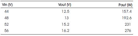
Table 1. Output Voltage and Power for Different input
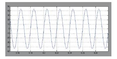
Figure 3.(a). AC input Voltage
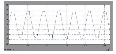
Figure 3.(b) Resonant Push Pull Converter Output Voltage
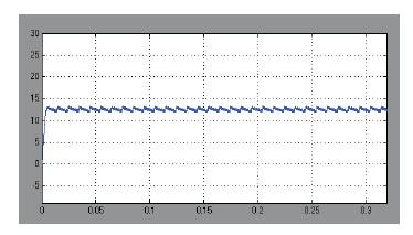
Figure 3.( C). Output Voltage (12V)
Figure 3.(d). Output Voltage (5V)
Multiple outputs AC to DC converter is modeled and simulated using Matlab simulink environment. As mentioned in abstract multiple outputs AC to DC converter are capable of giving 12V and 5V DC. This system has reduced steady state error. This converter has high power density. The simulation results are in time with the predictions. The advantages of this system are smaller transformer size and reduced filter size.