(1)
Feeder reconfiguration and capacitor placement are generally used for power loss reduction and voltage profile enhancement in radial distribution systems. This paper presents a joint optimization algorithm of combining feeder reconfiguration and capacitor placement for loss reduction. Genetic Algorithm (GA) is chosen to solve this combined optimization problem. The advantage of this method is that it can provide a global or near global optimum for feeder reconfiguration and capacitor placement. The effectiveness of the proposed method is illustrated with 33-node radial distribution system.
In the field of distribution automation, optimal reconfiguration and reactive power compensation allow the attainment of some important goals such as reduction of power losses, voltage profile flattening, improvement of power factor etc. Feeder Reconfiguration is defined as altering the topological structures of distribution feeders by changing the open/closed states of the sectionalizing and tie switches. The networks are reconfigured to reduce system real power loss, optimal linking of new loads, relieve overloads and service restoration.
Through the application of reactive power compensation one can reduce power loss, improve the voltage profile and quality of supply. Capacitors have been very commonly used to provide reactive compensation in distribution systems. The benefits of compensation depend greatly on the size of the capacitors added. Using switched capacitors we can vary the size of the capacitors installed on feeders.
These two methods are combined together to get much better effect of loss reduction. The early work on feeder reconfiguration for loss reduction is presented by Aoki.k et al. [1]. Baran and Wu [2] defined the problem for loss reduction and load balancing as an integer-programming problem. Chiang et al. proposed a solution procedure employing simulated annealing [3, 4] to search for an acceptable non-inferior solution. The other approach to feeder reconfiguration considering the ability of system transformers and power loss, and voltage profiles had been respectively presented [5-9]. Optimal capacitor placement is a combinatorial optimization problem that is commonly solved by employing mathematical programming techniques. Grainger and Lee [10-12] formulated the problem as a non-linear programming model that can be solved by simple iterative procedures based on gradient search. Su et al. [13] applied fuzzy reasoning approach to optimum capacitor allocation.
Most of the previous studies handled reconfiguration problem without considering the capacitor addition [19], [20] or handled capacitor compensation problems without considering feeder reconfiguration [10-14]. They dealt with the feeder reconfiguration and capacitor addition in a separate manner [1-14], which may result in unnecessary losses and cannot yield the minimum loss configuration. However only few papers on loss minimization applying heuristic techniques for feeder reconfiguration and capacitor placement had been presented[15-17].
In this paper, a joint optimization algorithm of combining feeder reconfiguration and capacitor placement to minimize power losses while satisfying all constraints is proposed. This joint optimization is done using Genetic Algorithm. The proposed method can attain a global or near global optimal feeder reconfiguration and capacitor setting.
In this section, mathematical formulation of network reconfiguration and capacitor placement of distribution systems is proposed. In both the cases, the aim is to minimize the power loss of the system satisfying the voltage and current constraints.
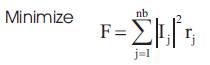
The purpose of distribution network reconfiguration is to find a radial operating structure that minimizes the system power loss under current carrying capacity and voltage limit constraints at the same time all loads are to be powered. Thus network reconfiguration for loss minimization can be formulated as follows.
Subject to the following constraints
(i) Radial network constraint:
Distribution network should be of radial structure.
(ii) Node voltage constraint:
Voltage magnitude at each node must lie with in their permissible ranges to maintain power quality;
where,
 = Voltage at node 'i'
 are minimum and maximum limits of voltage of node 'i'
( iii) Branch current thermal stability constraint:
Current magnitude of each branch must lie with in their permissible range
Where  is the maximum limit of current passing through branch 'j'.
The objective function is to maximize the net savings function (S) by placing the capacitor and is given as
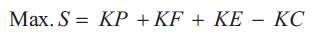
where,
S = Net Savings (Rs.)
KP = Benefits due to released demand (kW)
KF = Benefits due to released feeder capacity (kVA)
KE = Benefits due to saving in energy (kWh)
KC = Cost of installation of the capacitor (Rs)
(a) Benefits due to reduced demand
The benefits due to reduced demand is given by
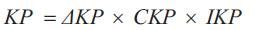
where,
ΔKP = Reduced demand (kW)
CKP = Cost of generation (taken as Rs. 10,000/kW)
IKP = Depreciation cost for generation (taken as 0.2)
(b) Benefits due to released feeder capacity.
The benefits due to released feeder capacity is given by
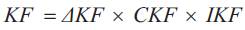
where,
ΔKF = Released feeder capacity
CKF = Cost of the feeder (taken as Rs. 171.5 /kVA)
IKF = Depreciation cost of feeder (taken as 0.2)
(c) Benefits due to savings in energy
The benefits due to savings in energy is given by
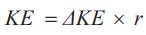
where,
ΔKE = Savings in energy
= (Annual energy losses before installing the capacitor)- (Annual energy losses after installing capacitor)
r = Cost of energy (taken as Rs 3/kWh).
(d) Cost of installation of capacitor
where,
QC = Total kVAR
ICKC = Cost of capacitor (Rs 200 /kVAR)
IKC = Depreciation cost of capacitor (taken as 0.2)
The GA based algorithm for reconfiguration and capacitor placement is explained below.
| Step 1: | Read system data |
| Step 2: | Create Initial population, Gen=1 |
| Step 3: | Initialize population size ,PS =1 |
| Step 4: | Alter the switch status and reconfigure the network |
| Step 5: | Perform the load flows |
| Step 6: | Evaluate fitness |
| Step 7: | Is initial population equal to population size, if yes go to Step 8, else increment PS by one and go to Step 4 |
| Step 8: | Create new population by crossover and mutation |
| Step 9: | Next generation |
| Step 10: | Is generation is of maximum generation. if yes print the result, else increment gen. by one and go to Step 3 |
| Step 11: | Stop |
The GA based capacitor sizing algorithm is given as:
| Step 1: | Generate the random population for size(s) of capacitors for Gen =1. |
| Step 2: | Perform load flows and determine various node voltages, active power loss. |
| Step 3: | Calculate the fitness function using Eqn. (2) |
| Step 4: | Select best strings from old population. |
| Step 5: | Perform cross over and mutation on the selection strings and obtain new strings for next generation. |
| Step 6: | Repeat steps 2 to 5 until the generation reaches the maximum generation and print the results. |
| Step 7: | Stop. |
In this study, an approach for feeder reconfiguration and capacitor sizing for distribution systems is proposed. The aim is to minimize the power loss of the system, subject to load and operating constraints.
The distribution system reconfiguration problem for loss minimization is to decide the position of sectionalizing switches and tie switches under the current capacity and voltage limit constraints at the same time when all loads are to be powered.
The objective of the capacitor placement problem is also to reduce the active power loss of the system, the same as the feeder reconfiguration. Network reconfiguration and capacitor placement are two important means in reducing the power loss of distribution system. If these two means are combined together, it is almost certain that much better result can be obtained. With this idea the program that can perform both the tasks is developed. After feeder reconfiguration, the original scheme of capacitor placement is probably not the best one under new network topology, so a new type of feeder reconfiguration and capacitor placement is adopted. Figure 1 shows the flowchart for combined optimization problem.
The effectiveness of the proposed method for combined optimization is illustrated with 33-node, 12.66 kV, radial distribution system [19].
This example can be explained with four different cases as follows:
Case I: Only feeder reconfiguration is considered
Case II: Only capacitor placement is considered
Case III: Both capacitor placement and feeder reconfiguration are considered. However, capacitor placement is carried out before feeder reconfiguration.
Case IV: Both capacitor placement and feeder reconfiguration are considered and are taken into account simultaneously.
The summary of test results of 33- node system with different cases is given in Table 1. From Table 1 it is observed that combined optimization of radial distribution system gives more loss reduction compared to individual optimization. The voltage regulation is also improved for combined optimization.
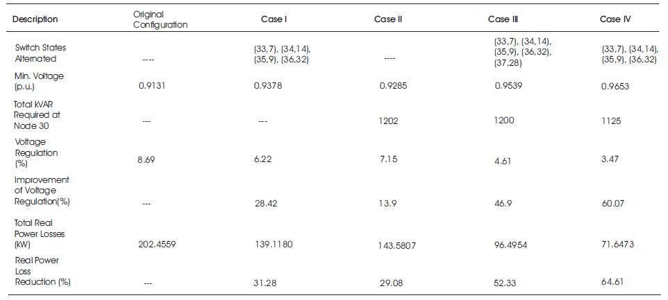
Table 1. Summary of test results of 33-node system
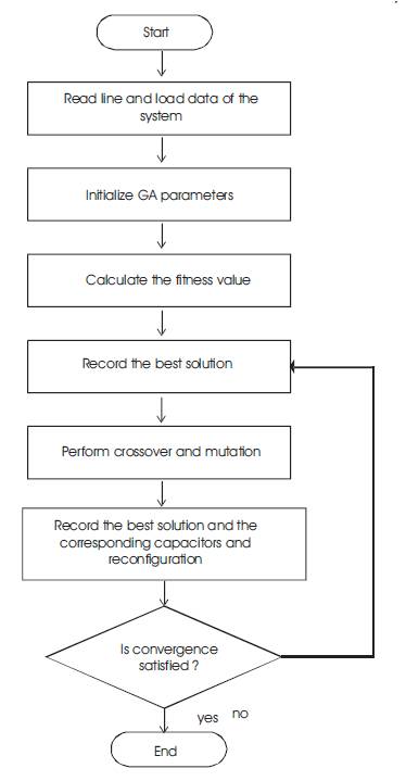
Figure 1. Flow chart for combined optimization problem
A useful feeder reconfiguration and capacitor placement problems employing genetic algorithm method for loss reduction of distribution systems was presented. The two important means of reducing the power loss of distribution system are combined together in order to obtain better optimization result. The algorithm has high efficiency in power loss reduction and improvement in voltage profile. The proposed method can be applied for different systems. The results show that it has a good performance and suitable for online application. From the results, considering both feeder reconfiguration and setting of capacitor, simultaneously we can generate more loss reduction than considering them separately. In addition to power loss reduction, the voltage profile can be improved as well by the proposed method.