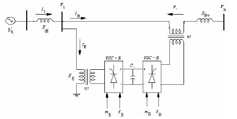
Figure 1. UPFC Installed in Single Machine Infinite Bus System
Figure 1 shows single-phase, schematic diagram of the power circuit of a UPFC which is composed of an excitation transformer (ET), a boosting transformer (BT), two three phase GTO based voltage source converters (VSCs), and a dc link capacitor [1] . The four input control signals to the UPFC are mE , mB , δE and δB. Where, mE is the excitation amplitude modulation ratio, mB is the boosting amplitude modulation ratio, δE is the excitation phase angle and δB is the boosting phase angle. By applying Park's transformation and neglecting the resistances and transients of the ET and BT, the UPFC can be modeled as [1-6] ,
The d-q axes voltage components of excitation transformer (E.T) and boosting transformer (B.T) are represented as
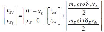
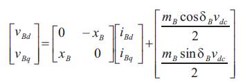
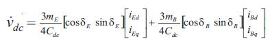
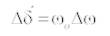
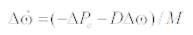
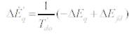
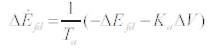
Where, VE, iE , VB and iB are the excitation voltage, excitation current, boosting voltage and boosting current respectively. Vdc is dc link voltage. The nonlinear model of dc the SMIB system with UPFC as shown in Figure 1 is described by,
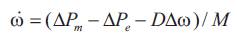
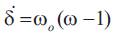
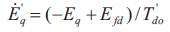
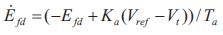
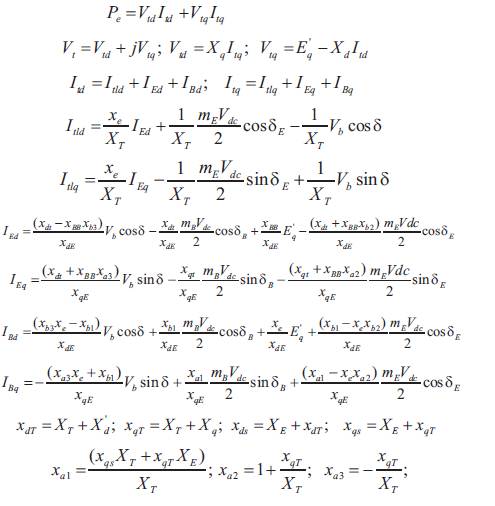
Where,
The equation for real power balance between the series and shunt converters is given by:
Where,
VB ,VE are the voltages of boosting transformer and excitation transformer.
IB ,IE are the currents of boosting transformer and excitation transformer.
2. Power system linearised model
A linear model is obtained by linearizing the nonlinear model around an operating condition . All the Kconstants of the model depend on the system parameters and the operating condition. The linearised model of the power system as shown in Figure 1 is given as follows:
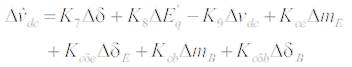
Where,
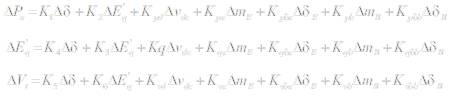
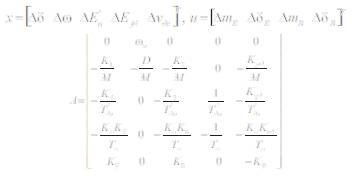
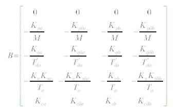
K1 - K9 , Kpu , Kqu , Kvu and Kcu are the linearization constants. The state-space model of power system is given by
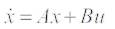
Where, the state vector x, control vector u, A and B are:
The block diagram of the linearised dynamic model of the SMIB system with UPFC is shown in Figure 2.
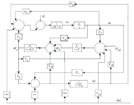
Figure 2. Modified Heffron-Phillips Transfer Function Model
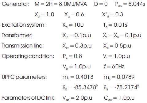
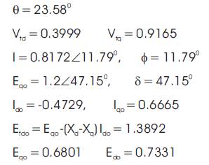
Before designing the controller, it is necessary to compute the initial d-q axes voltages and current components, torque angle and other system parameters at the specified operating condition. Therefore, the system parameters computed are [7]:
The K - constants of the model computed for nominal operating condition and system parameters are
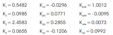
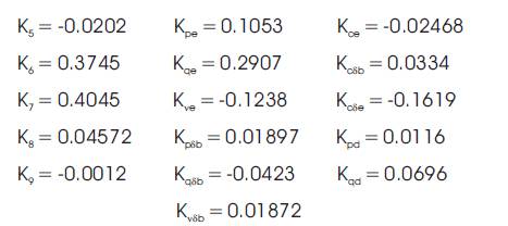
For this operating condition, the eigen values of the system are observed and it is clearly seen that the system is unstable.
3. Design of Damping Controllers
The damping controllers are designed to produce an electrical torque in phase with the speed deviation. The four control parameters of the UPFC i.e., mE , mB , δE and δB can be modulated in order to produce the damping torque. The speed deviation Δω is considered as the input to the damping controllers. The four alternatively UPFC based damping controllers are examined in this work.
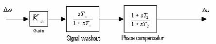
Figure 3. Structure of UPFC based Damping Controller
Damping controller based on UPFC control parameters mB shall henceforth by denoted as damping controller (mB ). Similarly damping controllers based on mE , δE and δB shall be denoted as damping controller (mE ). damping controller (δE) and damping controller (δB) respectively. The structure of UPFC based damping controller is shown in Figure 3. It consists of gain, signal washout and phase compensator blocks. The parameters of the damping controller are obtained using the phase compensation technique [8]. The detailed step-by-step procedure for computing the parameters of the damping controllers using phase compensation technique is given below:
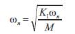
1. Computation of natural frequency of oscillation ωn from the mechanical loop
2. Computation of ∠GEPA (Phase lag between Δu and ΔPe ) at s = jωn. Let it be y.
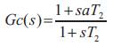
3. Design of phase lead-lag compensation Gc: The phase lead-lag compensator Gc is designed to provide the required degree of phase compensation. For 100% phase compensation,
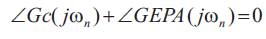
Assuming one lead-lag network, T1 = aT2 , the transfer function of the phase compensator becomes,
Since the phase angle compensated by the lead-lag network is equal to –y.
The parameters a and T2 are computed as,
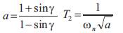
4. Computation of optimal gain Kdc . The required gain setting Kdc for the desired value of damping ratio = 0.5 is obtained as,
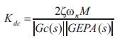
Where |Gc(s)| and |GEPA(s)| are evaluated at s = jωn
The signal washout is the high pass filter that prevents steady changes in the speed from modifying the UPFC input parameters. The value of the washout time constant Tw should be high enough to allow signals associated with oscillation in rotor speed to pass unchanged. From the viewpoint of the washout function, the value of Tw is not w critical may be in the range of 1s to 20s. Tw = 10s is chosen for the present case.
Figure 4 shows the transfer function of the system relating component of electrical power (ΔPe ) produced by e damping controller (mB ).
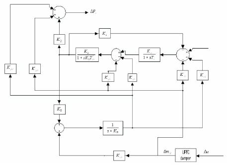
Figure 4. The Transfer Function of the System Relating component of Electrical Power (Δpe ) produced by Damping Controller (mB )
The time constants of the phase compensator are chosen so that the phase lead-lag of the system is fully compensated. For the nominal operating conditions, the natural frequency of oscillation ωn = 4.122 rad/sec. the transfer function relating Δpe and ΔmB is denoted as GEPA. For the nominal operating condition, phase angle of GEPA i.e., ∠GEPA = 9.0527o lagging. The magnitude of GEPA i.e. |GEPA|= 0.6789. To compensate the phase lead, the time constants of the compensator are obtained as T1 = 0.2860s and T2 = 0.2082s.
Following the same procedure, the phase angle to be compensated by the other three damping controllers are computed and are given in Table 1.
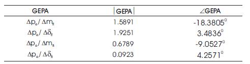
Table 1. Gain and Phase Angle of the Transfer Function GEPA
The critical examination of Table 1 reveals that the phase angle of the system i.e., ∠GEPA, is leading for control parameter δE and δB. However, it is lagging for mE and mB . Hence the phase compensator for the damping controller (δE) and damping controller (δB) is a lag compensator while for the damping controller (mE ) and damping controller (mB ) is a lead compensator.
The gain settings (Kdc ) of the controllers are computed c assuming a damping ratio = 0.5. Table 2 shows the parameters (gains and time constants) of the four alternative damping controllers. It shows the gain settings of the damping controller (mE ) and damping controller (δE) doesn't differ much. However, the gain setting of the damping controller (δB) is much higher as compared to the damping controller (mB ). Figure 6 shows the dynamic responses for Δω obtained considering a step load perturbation ΔPm, = 0.02pu with the following four alternative damping controllers are identical. At this stage it can be inferred that any of the UPFC based damping controllers provide satisfactory dynamic performance at the nominal operating condition.
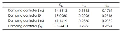
Table 2. Parameters of UPFC based Damping Controllers
4. Performance with UPFC Damper Controllers
The simulink model of SMIB with UPFC for damping controller mB is shown in Figure 5 whose damping parameters were computed and tabulated above. The variation of angular speed Δω with time for 0.02 p.u step change in mechanical power input Pm with four alternative damping controllers is shown in Figure 6. From the dynamic responses it is observed that δB and δE is more dominant compared to mB and mE in terms of overshot and settling time.
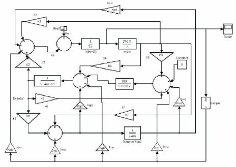
Figure 5. Simulink Model for SMIB with UPFC Damper Controller
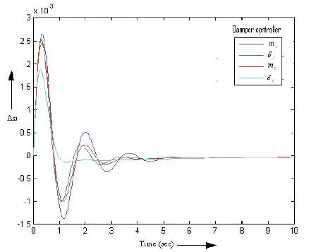
Figure 6. Dynamic responses for Δω Four Alternative Damping Controllers
5. Conventional PID Controller
The primary goal of a controller is to distill and apply knowledge about how to control a process so that the resulting control system will reliably and safely achieve high-per formance operation. Conventional PID controllers have been extensively used in industry, due to their effectiveness for linear systems, ease of design and inexpensive cost. PID controllers are versatile enough to control a wide variety of industrial processes. The common practice is to interface a PID controller to the process and adjust the parameters of the controller online by trail-and-error to obtain acceptable performance. In previous section we have designed damping controller now it is replaced by PID controller for all the four alternative control parameter of UPFC. The simulink models for PID controller based power system with UPFC controller mB is shown in Figure 7 whose parameters are obtained by trail-and-error method are tabulated as in Table 3.
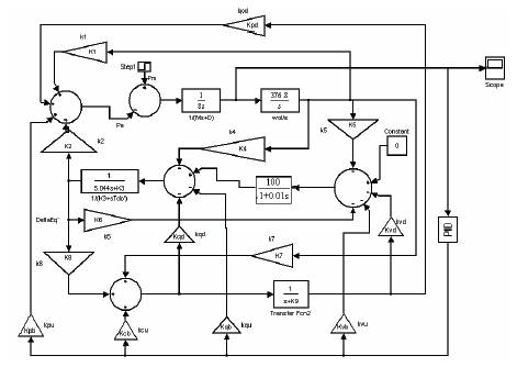
Figure 7. UPFC with PID Damper Controller
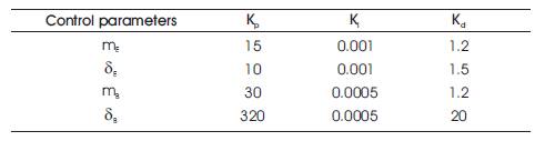
Table 3. Parameters of UPFC based PID Controllers
The variation of angular speed Δω with time for 0.02 p.u step change in mechanical power input Pm with four alternative PID controllers is shown in Figure 8. From the dynamic responses it is observed that δB anδE are more dominant compared to mB and mE . Variation of settling times between the damping controller and PID controller corresponding to four alternative UPFC parameters mE , mB , δE and δB, is less when compared to peak overshoot. So to damp the oscillations better we have adopted fuzzy logic controller.
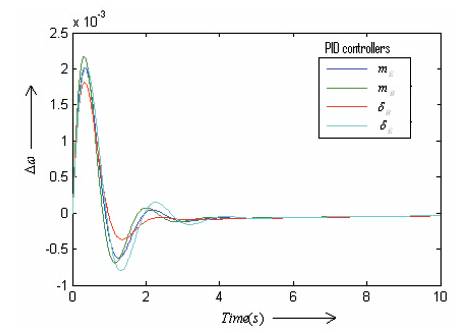
Figure 8. Dynamic responses for Δω with Time for 0.02 p.u change in Mechanical Power Input with four Alternative PID Controllers
6. Implementation of Fuzzy logic based UPFC
In order to damp of LFO effectively, fuzzy controllers are designed for UPFC inputs In the proposed method, Mamdani's fuzzy inference method is used, because it is the most commonly employed fuzzy methodology [9-11]. After the aggregation process, there is a fuzzy set for each output variable and finally they need to be defuzzificated. Angular velocity deviation (Δω) and load angle deviation (Δδ) are used as the fuzzy controllers inputs. One of the UPFC parameters (mB , mE , δB and δE) has been controlled via fuzzy controller is shown in Figure 11. For instance, the membership functions for the inputs and output of ΔmB fuzzy controller is shown in Figures 9 and 10. Membership functions for the other controllers are similar to Figures 9 and 10. Each membership functions consist of seven fuzzy subsets. The scaling factors of fuzzy controller Kin1, Kin2 and Kout are normalized in order to match the range on in out which the membership functions are defined.
The rules table for mB fuzzy controller is shown in Table 4 and is similar for other fuzzy controllers.
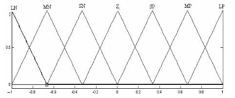
Figure 9. Input Membership Functions
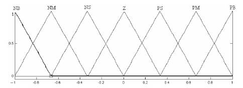
Figure 10. Output Membership Functions
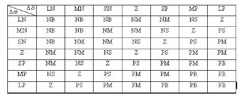
Table 4. Rule Base of Fuzzy Controller
Figure 11 shows the block diagram for fuzzy logic based power system with UPFC controller mB . In the proposed method, Mamdani's fuzzy inference method is used, because it is the most commonly employed fuzzy methodology [9]. Angular velocity deviation Δω and load angle deviation Δδ used as the fuzzy controllers inputs. Figure 12 shows the dynamic responses for angular speed Δω with time for 0.02 p.u step change in mechanical power input Pm with four alternative controllers. From the dynamic responses it is observed that δB and δE are more dominant compared to mB and mE .
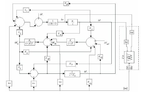
Figure 11. Block Diagram of Modified Heffron- Phillips Model with Fuzzy Logic Controller
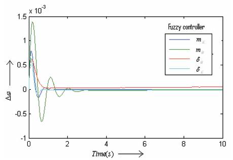
Figure 12. Dynamic responses Δω for with Time for 0.02 p.u Change in Mechanical Power Input with Four Alternative Controllers
7. Comparison
During step change in mechanical power (ΔPm= 0.02p.u) performance of the designed fuzzy logic controllers, PID controllers and damper controllers have been simulated and compared. The simulation is performed using MATLAB/SIMULINK software. The simulation is performed with the step change in mechanical input power, but the UPFC has controller for different cases.
In the first case the UPFC is equipped with the damper controller and in the second case the UPFC has conventional PID controller and finally the UPFC is equipped with fuzzy controller. The results of simulation with controller mE for the three cases are shown in Figure 13. In Figure 13, the simulation is performed by controlling the input mE of the UPFC. Figures 14 to 16 show results of the designed controller for δE, mB and δB UPFC inputs respectively. Simulation results show that fuzzy logic controller successfully increases damping rate and decreases the amplitude of low frequency oscillations. Results comparison between damper controllers, conventional PID controller and the proposed fuzzy for the UPFC indicates that the proposed fuzzy controller has less settling time and less overshoot and compared with the other controllers.
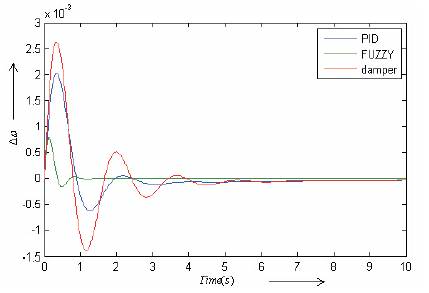
Figure13. Dynamic Response for Δω with Controller mE
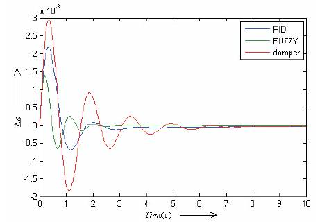
Figure 14. Dynamic response for Δω with controller mB
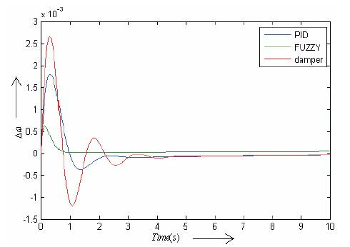
Figure 15. Dynamic response for Δω with controller δB
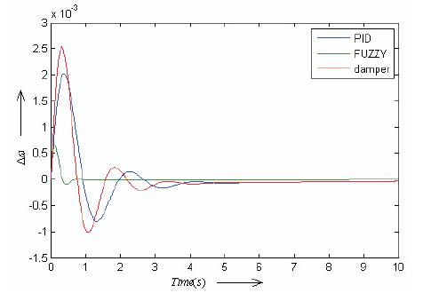
Figure 16. Dynamic response for Δω with controller δE
Conclusion
The objective of this work is to damp the oscillations of the power system using a fuzzy logic theory on single machine infinite bus system with UPFC. The proposed controller provides a more robust control over the conventional damping and PID controllers. In this thesis the effect of damping controllers (phase compensation) and PID controllers in damping the power system oscillations are reviewed then the fuzzy based controller is introduced with angular speed deviation Δω and rotor angle deviation Δδ of the generator as input signals to the fuzzy controller and one of the UPFC control parameter mE , mB , δB,δE, as output signal. From the simulations it is studied that fuzzy based δB and δE control parameters provides dominant performance compared to other control parameters like mB and mE at the given operating condition and system parameters. This method can also be extended for the multi machine systems. The oscillations can be quenched in a optimal manner by simultaneously controlling the four control signals of UPFC.
Appendix