Figure 1. Illustration of Controllability of Power Systems
This paper describes closed loop controlled inter Line Power flow controller used in power system. An Inter line power flow controller is VSC-based FACTS controller for series compensation with the unique capability of power management among multilines of a subs-station. The FACTS technology is essential to alleviate these difficulties by enabling utilities to get most service from their transmission facilities. FACTS controllers can control series impendence, shunt impedance, current, voltage and phase angle. Different FACTS controller's circuits are simulated using PSPICE software package.IPFC is used to improve the power flow and to provide a power balance of a transmission system. The circuit model of IPFC was developed and the same is used for simulation.
As a result of Flexible AC transmission system, considerable effort has been spent in recent years on the development of power electronics based power flow controllers [1]. They employ self-commutated inverters as synchronous voltage sources. The power electronics based voltage sources can internally generate and absorb reactive power without the use of capacitors and reactors. They can facilitate both real and reactive power compensation and thereby can provide independent control for real and reactive power flow [2, 3].
The Interline Power Flow Controller (IPFC) scheme proposed provides, together with independent controllable reactive series compensation of each individual line, a capacity to directly transfer real power between the compensated lines. This capability makes it possible to equalize both real and reactive power flow between the lines; transfer power demand from overland to under loaded lines; compensate against resistive line voltage drops and the corresponding reactive power demand; increase the effectiveness of the overall compensating system for dynamic disturbances[4-9]. The IPFC can potentially provide and effective scheme for power transmission management at a multi-line substation. In the present work ,the circuit model for closed controlled IPFC is developed and the same is used for simulation.
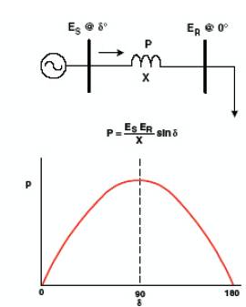
To illustrate that the power system only has certain variables that can be impacted by control, consider the basic and well-known power-angle curve, shown in Figure 1. Although this is a steady-state curve and the implementation of FACTS is primarily for dynamic issues, this illustration demonstrates the point that there are primarily three main variables that can be directly controlled in the power system to impact its performance. These are
One could also make the point that direct control of power is a fourth variable of controllability in power systems. Consider the basic and well-known power-angle curve, shown in Figure 1.
Figure 1. Illustration of Controllability of Power Systems
Recently, some new devices have been put forward within the FACTS technology, the IPFC (Interline Power Flow Controller). By utilizing these device, an independent controllability over each transmission line of a multi-line system, can be achieved. With the cost of the high power semiconductors and converters declining steadily, the IPFC (Figure 2) appear as a stand out solution for the power flow control of multi-line systems, instead of using individually controlled UPFCs (Unified Power Flow Controller) in each line.
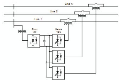
Figure 2. The IPFC System for Multi-line Power Flow Control
The IPFC steady-state operation also requires that the sum of the active power, exchanged by the total number of converters, be zero. Under certain conditions such as when no voltage support in the substation bus is required, the shunt converter can be dispensed with and the (now an IPFC) will be basically constituted by SSSCs (Static Synchronous Series Compensators) connected one to another through a common DC capacitor. In this case, the real power required for varying the angular position of the series voltages, will have to be supplied from one of the compensated AC systems. Under the configurations (IPFC), the primary inverter(s) or assisted system(s), will have priority over the secondary inverter (within the assisting system) in achieving its set-point requirements.
The steady-state analysis developed in this section considers an IPFC linking two balanced independent AC systems Figure 3. For ease of analysis, the equivalent sending and receiving-end sources in both systems were regarded as stiff AC sources (infinite buses). It was also assumed that Systems 1 and 2 (or primary and secondary systems, respectively) have identical line parameters, although in practice they would usually be different. For heavy and simultaneous compensation in both systems, the shunt converter will have to be properly rated so as to attend the requirements of all the series inverters in operation. Another assumption regarded in this section is that each converter behaves as a shunt or series source operating with fundamental frequency and characterized by ideal sinusoidal waveforms.
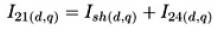
The power equality between the shunt and the series inverters, so as not to absorb and generate active power from or to the AC system, was strictly applied to the model. Thus, it can initially be established that,
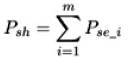
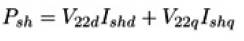
In (1), m stands for the total number of series converters. In our case m=2, therefore, using the ds - qs orthogonal components of Ish and V22 for the real power Psh (derived from bus V22 ), it can be written as,
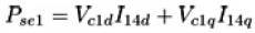
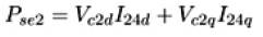
Similarly, the real power injected or absorbed by the series converters, regarding Vc1 (Vc2) and I14 (I24), will be,
Likewise, the reactive power injected (or absorbed, depending on the mode of operation) by the shunt converter can be expressed as,

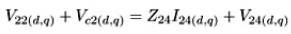
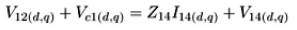
So, from Figure 3 the following relations for Systems 1 and 2 can be written as,
Regarding the shunt current, Ish, as being derived from bus V22 ,
also

similarly for System 1,

Equations (6) through (10) are represented in a simple way only to shorten the set of equations. In order to relate them to eqs. (1) and (5), they should also be written in their ds - qs components, which in this case coincide with the real and imaginary axis. By manipulating equations (1) through (10), it will be obtained a set of 10 equations (some of them non-linear) that can be solved using any iterative method. Once computed the unknown variables (i.e. the d -q components of V12 , V22 , Ish , I14 , I24 ), the power flow in the receiving-end of Systems 1 and 2, with or without the series and shunt compensation effect, can be easily calculated through (11). The horizontal line above each variable in (11) and (12) denotes that such variables are phasors.
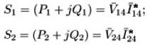
In this model, the inclusion of the series transformers' coupling reactance Xse(1,2) within impedances Z14 and Z24 was only done to shorten the system equations. Once computed the line current (I14), the voltage V13 can be calculated through (12). The bus voltage V23 (System 2) can be obtained through a similar procedure.

The IPFC mathematical model developed in this section is also valid for the case of a classical IPFC configuration. Since the shunt VSI is no longer present in the secondary (assisting) system, some of the variables in the above equations will have to be zeroed (i.e. Ishd =0, Ishq =0 and Qsh =0). Under this configuration, System 1 (master) will have two independently controlled variables i.e. Vc1 . Conversely, System 2 (slave) will have to provide the series real power demanded by System 1, thus, leaving only one variable (Vc2q) to be independently controlled. The above description implies that for the case of a classical IPFC scheme, the real power exchange of converter 2 is predefined (i.e. there exists a constraint for System 2) and therefore, only its series reactive compensation can utterly be utilized to control the power flow in this line (similar to the action of an SSSC).
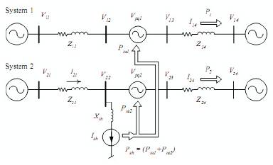
Figure 3. Elementary IPFC System
The circuit model of IPFC is shown in Figure 4. In this model, the series transformers are represented as voltage depended voltage sources. The real power waveform without IPFC is shown in Figure 5. The real power wave form with IPFC is shown in Figure 6. From Figure 6, it can be seen that the real power is increased.
Figure 4. Circuit Model of IPFC with Phase Difference
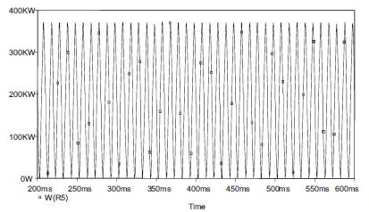
Figure 5. Real Power without IPFC
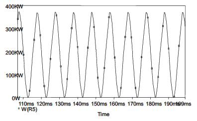
Figure 6. Real Power with IPFC
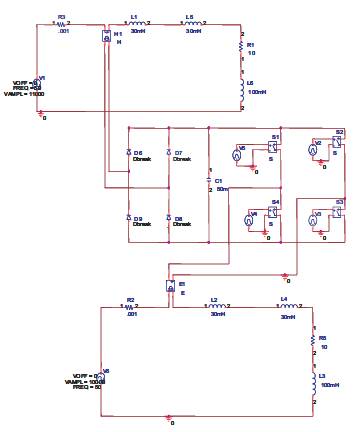
Figure 7. Circuit Model of IPFC with different Voltage
The circuit model of IPFC with different values of voltages is shown in Figure 7. Lines 1&2 operate at 11kv and 10kv respectively.
From the Figure 9, it can be observed that the Reactive power is increased.
Figure 8. The Reactive Power without IPFC

Figure 9. The Reactive Power with IPFC
The circuit model with different phase angles is shown in Figure 10. Sources at lines1 and 2 operate at 20o and 30o respectively. Real and reactive powers in line1 are shown in Figures 11&12 respectively. Real and reactive powers in line2 are shown in Figures 13 & 14
The closed loop controlled IPFC system with phase angle difference between two lines is shown in Figure 15. Two transmission lines, one with phase angle 0° and other with the 20° is considered. Sending end voltages are sensed and they are applied to the compensator. The output of the compensator is rectified using a rectifier. The different between compensator output and reference voltage are amplified by a differential amplifier. This output controls the switch in the IPFC.
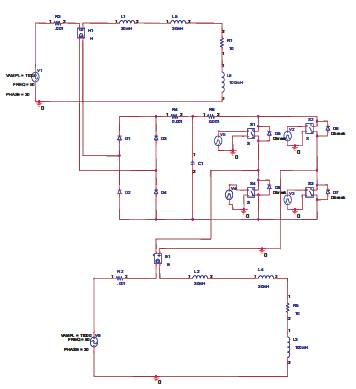
Figure 10. Circuit Model with different Phase Angles.
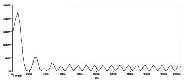
Figure 11. Real Power in Line1
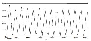
Figure 12. Reactive Power in Line1
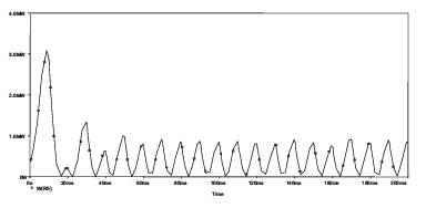
Figure13. Real Power in Line2
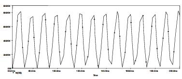
Figure 14. Reactive Power in Line2
The real power with and without compensation over loaded line is shown in the Figures 16 & 17. From Figures 16 & 17 it can be seen that real power drawn from the source with compensation is less than the real power drawn from the source without compensation. Figure 18 shown that input power in the normal load line with compensation.
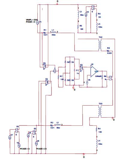
Figure 15. Circuit Model of Closed Loop System with Phase difference
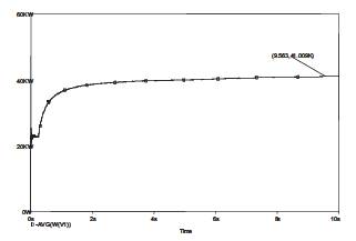
Figure 16. Power in the Over Loaded Line with Compensation
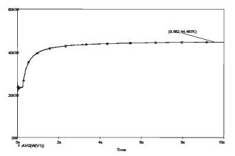
Figure 17. Power of Over Loaded Line without Compensation
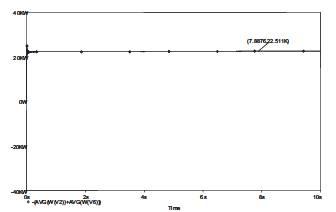
Figure 18. Power in the Normal Loaded Line with Compensation
A new circuit model for IPFC with phase difference is developed and the same is simulated to study the real and reactive power flows. The circuit model for open loop and closed loop systems are presented. They are used to simulate the two line system to study real and reactive power flows .It is observed that the real and reactive powers are increased by the presence of IPFC. The IPFC is a viable solution to balance the power flow in a transmission system.