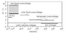
Figure 1. Representative Maxima of Amplitude of Overvoltages Urp (per unit values)
2.1 Temporary overvoltages
Temporary overvoltages arise from single-phase earthfaults on the two unfaulted phases or from load rejections on all three phases, if the load remaining on the generators is not sufficient to avoid over excitation. Their duration is in the order of 1 s.
Temporary overvoltages represent stresses to the internal insulation, for example of transformers. In addition, temporary overvoltages are the basis for the selection of the surge arrester ratings. From both points of view low temporary overvoltages have to be aimed for Per unit values of 1.3 or even less are considered suitable.
Temporary overvoltages may also occur due to resonance and ferro-resonance phenomena in particular when energizing transformers via longer lines or de-energizing inductive voltage transformers [5] . These voltages can last for more than 10 s. Therefore a sufficient damping of the oscillation has to be obtained.
2.2 Slow-front overvoltages
Slow-front overvoltages are of particular importance for UHV systems because of the saturation effect of the switching impulse strength of the air insulation due to the enhanced leader propagation in air in the frequency and voltage steepness range in question. Slow-front overvoltages of interest arise from
- Earth-Fault Initiation and Earth-Fault Clearance
- Energization and Re-Energization of Lines after Faults.
For UHV systems overvoltages due to earth-fault initiation and clearance are of predominant importance. Overvoltages due to earth-fault initiation occur on the unfaulted phases and may cause a subsequent failure on these phases not necessarily on the same line. The consequence could be loss of two lines at one earth-fault.
Overvoltage due to fault clearing occurs on the faulted phase, when the faulted line is switched off. A subsequent insulation failure may occur on the part of the system still in operation. Both types of overvoltages should be carefully investigated for a given system, because they cannot be avoided by protection means. The amplitudes of such overvoltages are proportional to the earth-fault factor and may reach 1.5 p.u for earth-fault factors of 1.25 to 1.3.
Overvoltages due to energization and, in particular, reenergization of overhead lines after faults have to be limited. Suitable means like pre-insertion resistors or point of- wave switching are available. An especially severe situation is obtained for three-phase re-energization due to the trapped charges remaining on the two unfaulted phases, when the fault is cleared. There are two possibilities to avoid such trapped charges:
2.2.1 Single-Phase Reclosing
Only the phase on which an earth-fault occurred is switched-off. As this phase is earthed by the fault, no trapped charges will be present at re-energization.
However, during the fault an appreciable current will flow through the fault due to capacitive coupling from the two sound phase conductors. This current may prevent the earth-fault from extinguishing resulting into an unsuccessful reclosure. For estimation, if the secondary arc will be extinguished, simulations can be performed using an arc model simulating the free in air burning arc and an adequate line model taking into account the travelling wave and the damping phenomena of the line [6] .
2.2.2 Fast three-Phase Earthing of the Overhead line
The trapped charges will be diverted to earth by the earthing switch. The switching sequence after earth fault would be opening of the line breaker, closing of the earthing switch, opening of the earthing switch and closing of the line breaker. It is evident that the fault clearing time will be long.
If one of the two methods or an alternative method is successful, the overvoltages due to line energization should be limited to the overvoltage due to earth-fault initiation and clearing. Preinsertion resistors and point-ofwave switching are most suitable to obtain overvoltages in the order 1,5 p.u.. Only specially designed surge arresters [7] have protective levels in such low order, but the surge profile along the transmission line has to be observed.
2.3 Fast-Front Overvoltages
Fast-front overvoltages are caused by
- Disconnector Switching in Substations
- Lightning Strokes to Overhead Lines.
Disconnector switching in substations can have overvoltage amplitudes up to 2.5 p.u.. If metal-oxide surge arresters are installed on the part of the substation switched-off by the disconnector the overvoltage will be limited to the protective level of the arrester. If not, the insulation has to be designed for this value.
Lightning strokes hitting UHV transmission lines can generate overvoltages of several MV [8] depending on the impinge surge and the height of the tower. Both shielding failures as well as back-flashovers have to be taken into account. Methods for estimation of lightning performance of transmission lines are given in [9] . For shielding analysis the leader propagation model and the Electro-Geometric Model (EGM) are applied. For a first estimation the simplified EGM seems to be sufficient. For determination of back-flashovers the tower surge response and the earth electrode impulse response have to be considered. For simulation of the tower surge impedance a “wasted tower shape” is assumed. The footing impedance can be simulated by a current dependent resistance.
If the potentials at the tower exceed the line insulator strength a flashover occurs. The flashover voltage can be derived from the voltage time curve using the equal area criterion or the leader development method. The lightning current will be represented by a concave or a ramp wave form regarding the different steepnesses and amplitudes for the first stroke and the subsequent strokes.
Due to these phenomena UHV transmission lines will have a very high lightning impulse flashover voltage of several MV. Even if the overhead line shielding has been designed for small shielding failure rates high lightning overvoltages will reach the substations and cause high overvoltages at the equipment. Protection by surge arresters has to be designed as an economical optimum between the required lightning impulse withstand voltage of the insulation and the number of surge arresters to be applied. For Lightning overvoltage analysis of the substation adequate line modelling by frequency dependent models including corona damping have to be used.
The analysis has also to regard the spatial dimensions of the substation and the location of the arresters to obtain the correct overvoltage profile in the substation.
2.4 Very Fast-Front Overvoltages
Very fast-front overvoltages are caused in SF6 gas insulated substations (GIS) in two ways [9] :
- Switching operations, mainly disconnector switching
- Line to enclosure breakdowns
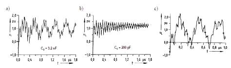
Figure 2. Very fast front overvoltage during disconnector switching in GIS a) With large source side capacitance (e. g. capacitive VT) b) With lower source side capacitance (e. g. surge arrester) c) With multi-break circuit breaker under out of phase conditions
During disconnector switching when switching short bus ducts at a residual DC voltage [10] of 1 pu the following values will occur:
- 1.9 pu with large source side capacitance (about 2…3 nF), e. g. capacitive VTs (Figure 2a)
- 1.5 pu with lower capacitances of some hundred pF, e. g. surge arresters (Figure 2b)
For disconnector switching in connection with a capacitively graded multi-break circuit breaker under out of phase conditions values of
- - 2.0…2.2 pu may occur at which a high damping of the VFT component by the grading capacitor is to be considered (Figure 2c).
Line to enclosure breakdowns primarily occur due to flashovers within the GIS and could lead to a subsequent breakdown at defects. Since these flashovers are mainly caused by defects with a strongly inhomogeneous field the voltage collapse results in a strong damping which is additionally enhanced by the fault arc. Therefore no subsequent breakdown has to be expected, even if the breakdown voltage is only weakly reduced compared to sound conditions.
3. Dielectric Strength of Insulation
3.1 Dielectric Strength at Operating Voltage
It is evident that the dielectric strength at operating voltage has to be withstood by the equipment during its life. Concerning the internal insulation of apparatus the experience of manufacturers based on the operation at smaller voltage levels has to be extrapolated to the higher voltage levels in the UHV range.
UHV transmission is selected to transport power over long distances. The most expensive parts of this transmission system, therefore, are the overhead lines which have to be designed for the economic optimum.
As far as insulation is concerned, insulator design according to the expected pollution level is a priority task. Since long time the investigation of the pollution performance of insulators is a priority task of CIGRE. Remarkable progress has been achieved, the results of which can be summarized as follows,
- The pollution withstand voltage of insulators is proportional to the specific creepage distance irrespective the insulator length. The necessary creepage distance depends on the pollution severity as given in IEC 60071-2 or IEC 60815. It is, for example 20 mm/kV for medium pollution, where the value is referred to the highest system voltage, usually equal to the highest voltage for equipment.
- The ratio of the creepage distance to the insulator length should not exceed 4, preferable 3.8.
Further guidance for selection and dimensioning of outdoor insulation is given in [11] . Composite insulators with silicon rubber housings or sheds present advantages with regard to design and pollution performance. They can supply the same creepage distance at shorter axial length compared to ceramics. As the material is hydrophobic they can provide a better pollution behavior as long as the hydrophobicity is maintained.
3.2 Dielectric Strength at Switching Impulses
The knowledge of CIGRE regarding the insulation withstand [12] is fully included in IEC 60071-2. The 50% flashover voltage of the insulation depends on a number of parameters from which the most important ones are:
- Gap Distance
- Gap factor describing the Gap Geometry
- Time-to-Crest of the Switching Impulse
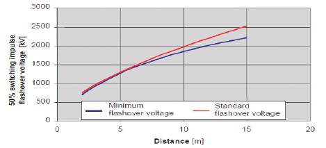
Figure 3. 50% switching impulse flash-over voltage of a rod-plane gap dependent on the gap distance For internal insulation the dielectric strength at switching impulses is usually of minor importance
Figure 3 shows the dependency of the 50% switching impulse flashover voltage of a rod-plane gap on the gap distance for the two parameters, the minimum value obtained for a specific time-to-crest and the standard value obtained for the standard switching impulse 250/2500 μs. For larger distances the two values deviate and the difference can result in quite different distances. In insulation co-ordination the influence of the time-tocrest has to be taken into account during the system analysis.
3.3 Dielectric Strength at Lightning Impulses
For practically all insulation the lightning impulse withstand is proportional either to the dielectric field strength (internal insulation) or to the distance (external insulation) and can be assessed with suitable accuracy in the design stage. In case of standard impulses the strength can be taken from experimental information. Once the gap factor of the arrangement under consideration is determined the flashover voltage can be derived from Figures 4 and 5 [12] .
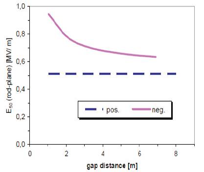
Figure 4. Average gradient E50 = U50 / d of a rod-plane gap in dence of the gap clearance for standard LI voltage
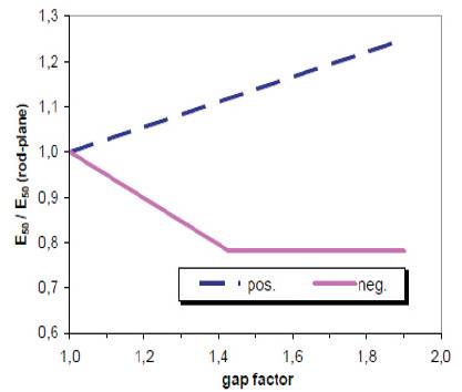
Figure 5. Average gradient E50 related to E50 rod-plane of a rod plane gap (Figure 4) in dependence of the gap factor
For evaluation of non-standardized impulses suitable models have to be applied to predict the strength. Two basic models are in use,
- The Integration Method which estimates the flashover voltage from the voltage time curve using the constant area criterion.
- The Leader Development Method.
3.4 Dielectric Strength at Very Fast Transient Stress
The VFT stress is of special interest with regard to SF6 insulated systems. Under sound conditions the VFT stress is covered by the withstand capability for standard LI voltage [13] . However, it has to be taken into account when choosing a relatively low lightning withstand level (LIWL) the margin between VFTO and LIOV becomes smaller. Figure 6 shows typical overvoltage probability densities along a 420 kV GIS [14] . The amplitude is related to a LIWL of 1425 kV according to the relevant apparatus standard which corresponds to a ratio of 4.2 pu to the normal service voltage. The overvoltage due to disconnector switching (VFTO) shows a maximum at 0.38 pu (related to the LIWL), whereas the maximum of the LIOV is at 0.65 pu. Assuming that the same overvoltage probability density will occur in a UHV SF6 insulated system with a LIWL of 2550 kV, the VFTO maximum will move to 0.52 pu (related to the LIWL) due to the smaller ratio between LIWL and normal service voltage of 3.1 pu.
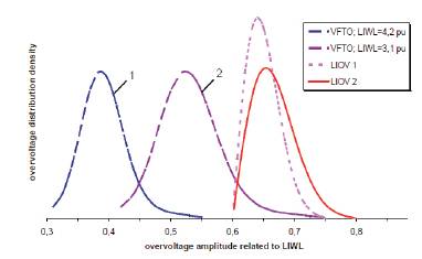
Figure 6. Typical overvoltage probability due to VFTO and LIOV (related to LIWL) along a GIS station 1: VFTO probability related to LIWL of 4.2 pu 2: VFTO probability related to LIWL of 3.1 pu
Furthermore, when selecting the insulation withstand level with respect to fast and very fast transient overvoltage stresses further aspects should not be disregarded, e. g.:
- The absolute number of occurrence of overvoltage processes caused by disconnector switching during the total lifetime of the equipment is in the range of some thousands up to ten thousand whereas the number of overvoltage processes due to lightning is in the range of some tens up to a few hundred.
- Overvoltages due to disconnector switching cannot be limited by arresters, as they are internal overvoltages. Nevertheless, a properly designed SF6 insulating system is able to withstand the transient and very fast transient overvoltages. Special attention has to be paid for when defects are present in the insulation system [14,15] . The field enhancement due to the defects gives considerably lower breakdown voltages. Failures even occurred due to disconnector switching generated VFTO, often in the vicinity of the disconnector itself or at the end of busbar sections.
Figure 7 gives an overview, how far the breakdown strength is reduced by fixed or moving particles [15] . In Figure 7(a), the 10% breakdown field strength depending on the particle length is shown for a fixed particle stressed by lightning, switching and AC voltage. Additionally different PD levels are given.
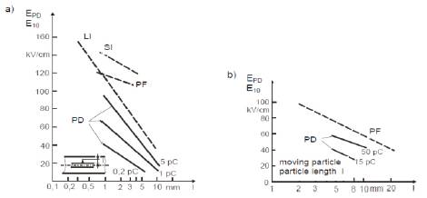
Figure 7. 10% breakdown field strength and PD field strength for defects a) Fixed particles b) Moving particles
The field strength related presentation is chosen to enable a more general assessment. The design field strength differs between the various manufacturers, but as a rule field strengths of 140...180 kV/cm are taken for LIWL, 110…145 kV/cm for SIWL and 70…115 kV/cm for PFWL. The field strength at normal service voltage is in the range of 30…45 kV/cm. The fixed particles are particularly critical at lightning overvoltage. The critical particle length is millimeter range. At switching and power-frequency overvoltage the critical particle length is distinctly larger. PD detection of the critical particles needs a rather high PD measuring sensitivity. Free moving particles are in particular critical at power-frequency voltage. The critical particle length is in the range of some millimeters. A measuring sensitivity of some pC is sufficient for a PD detection of critical particles at service voltage.
4. Insulation Co-ordination
Insulation co-ordination requires that the insulation withstands the voltage and overvoltage stresses in the system with a sufficiently low failure probability. In order to fulfill this insulation requirement the following criteria can approximately be applied (see IEC 60071-2):
- The co-ordination withstand voltage of the internal insulation (transformers, GIS) should be at least equal to the maximum overvoltage of a given category.
- The co-ordination withstand voltage of the external insulation should have a sufficiently low risk of flashover, which is for slow-front overvoltages assured, when the switching impulse withstand voltage is 1.05 times the 2% overvoltage value. The co-ordination withstand voltages are the voltages which the insulation has to withstand in all service conditions. However, the equipment is tested in standard conditions and the difference in dielectric strength arising from these conditions has to be taken into account by suitable factors:
- External insulation: Altitude correction up to 1000 m: Ka =1.13, Safety factor: Ks = 1.05
- Internal insulation: Safety factor: Ks = 1.15
When choosing the safety factor Ks for SF6 insulated systems to meet the co-ordination withstand voltage further aspects have to be taken into consideration which are particularly important for fast front voltages. This is the volume effect when determining Ks for complete substation derived from type testing on components or single bays. Furthermore the impacts of smaller defects like particles which can occur during the service life after commissioning and might decrease the insulation strength. The impact of the latter one might be reduced by adequate monitoring and diagnostic techniques. Therefore for fast front overvoltages in SF6 insulated systems Ks of at least 1.25 is recommended in [13] . This Ks factor should also be adopted for GIS in UHV systems. How far this subject has also to be considered for power transformers is under investigation [16] .
5. Basic Design of External Insulation
The required insulator length is determined by the specific creepage distance and the recommended maximum ratio between creepage distance and length of 3.8. For vertical insulators these values are approximately equal to the required distances. Figure 8 shows these distances for the medium pollution levels (20 mm/kV) and heavy pollution levels (25 mm/kV).
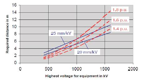
Figure 8. Required clearances for vertical insulators concerning insulator pollution (blue) for medium and heavy pollution and 2% value of slow-front overvoltages from 1.4 pu to 1.8 pu
As described in section 2.2 the required clearances to withstand slow-front overvoltages of a given pu value increase more than proportional with the highest voltage for equipment. Figure 8 shows these required distances for three values 1.4 pu, 1.6 pu and 1.8 pu for the 2% value for these overvoltages.
For a 1100 kV UHV system operating in areas with medium pollution the reduction of slow-front overvoltages down to 2% values of about 1.5 pu provides the optimum distance of about 5.5 m. If the system operates in heavy polluted areas a reduction of slow-front overvoltages to about 1.7 pu is sufficient. The optimum clearance is then about 7.2 m.
Concerning the insulation of open air substations the above statements fully apply. Concerning overhead lines in heavy polluted areas the use of V-strings as insulators may provide advantages in the clearances, when the slowfront overvoltages are reduced to 1.5 pu. A further reduction can only be obtained, when the overvoltages due to fault initiation and clearing are lower than the 1.5 pu as estimated in section 2.2.
Conclusion
When planning a new power system, in particular in the UHV range, Insulation Coordination (IC) is one of the most important subjects. The results have a strong impact on the reliability of the system and the economical expenditure. The general procedure is given in IEC 60071. Additional information in particular with regard to questions associated with a new voltage level can be taken from the CIGRE work. In the past, various CIGRE working bodies were involved in this subject and a lot of basic knowledge was gained.
For determination of the relevant stresses by simulation and estimation methods as well as for assessment of the dielectric strength reference can be made to various CIGRE publications [17] , some of them are given in the references. When designing a system in the UHV range transient stresses due slow, fast and very fast front overvoltages are of special interest. With respect to external insulation particular regard has to be given to switching overvoltages caused by single-phase autoreclosing, to lightning overvoltages due to shielding failures and back-flashovers. TOV due to resonances and ferro-resonances have to be considered thoroughly, since they can last for more than 10 s and may lead to inadequate stress of arresters and transformers or inductive Vts.
With respect to internal insulation, primarily SF6 gas insulation under sound but in particular with defects, special attention has to be paid to VFTO and LIOV. A reduction of the insulation level may increase the risk of breakdowns at disconnector switching and due to minor defects like particles in the insulation system. Therefore a Ks factor of 1.25 with regard to fast front overvoltages is recommended for SF6 insulation. The strength at operating voltage is essentially affected by the pollution withstand voltage of insulators. A ratio of the creepage distance to the insulator length of 3.8 is recommended which can easily be achieved by composite insulators due to their advantages under polluted conditions. A lot of information on pollution performance as well as on selection and dimensioning of outdoor insulation is provided in different CIGRE publications. Thus the experience collected by various CIGRE working bodies represents a reasonable basis for planning and designing an UHV system.