[1]
In the speed sensorless of the induction motor, the machine parameters (especially rotor resistance Rr) have a strong influence on the speed estimation. This paper presents an original method of estimating the rotor resistance of a conventional Indirect Stator Flux Oriented Controlled (ISFOC) induction motor drive. A Model Reference System (MRAS) has been formed to estimate the rotor resistance which is tuned to obtain high-performance ISFOC induction motor drive. The reference and adjustable models, developed in stationary stator reference frame, are used in the MRAS scheme to estimate induction rotor resistance from measured terminal voltages and currents. The IP gains speed controller and PI gains current controller are calculated and tuned at each sampling time according to the new estimated rotor resistance. The proposed algorithm has been tested by numerical simulation, showing the capability of driving active load; and stability is preserved. Experimental test have been carried out in order to validate the effectiveness of the proposed scheme. The controller was implemented on a digital signal processor based on dSPACE DS1104. The experimental resultants show the satisfactory behavior of the proposed approach in terms of dynamic performance.
Due to their simple structure, low cost and great reliability, induction motors are widely used in applications requiring high dynamic performance. Control techniques of these drivers are well treated in the literature. Indirect Field- Oriented Control (IFOC) method appears to be very convenient for good dynamic response [1] . By providing decoupling of torque and flux control demands, the vector control can navigate an AC motor drive similar to a separately excited DC motor drive without sacrificing the quality of dynamic performance [2] .
A high performance vector control scheme needs rotor speed information to achieve a speed feedback control [3] . Within this scheme, a rotational transducer was often mounted on the induction motor shaft. However, the implementation of speed sensors would greatly reduce the reliability of system, increase system cost and even could not be mounted in some hostile environment. Therefore, sensorless Induction Motor (IM) drives are widely used in industry for their reliability and flexibility, particularly in hostile environment
Usually the estimation of speed is achieved by assuming that the rotor resistance is constant throughout the operating range. In practice, the rotor resistance changes dramatically with temperature and frequency [4-7] . A very important variation of this parameter affects the performance of estimators of the stream. Indeed, the rotor resistance is involved in the analytical expression of decoupling of the component of torque producing current and charge flow. It is therefore clear that if this parameter varied between decoupling the flow and the electromagnetic torque will be more assured of or deterioration of performance training [8] .
To overcome the above problem an estimation of the rotor resistance is required first. Several algorithms for the rotor resistance estimation have been developed during the last years in order to overcome this problem [7]-[11] . In [9] the rotor resistance was estimated from the extended Kalman filter. The method used is limited to steady-state operation and the estimator designed is based on a linearized induction motor model. In references [10]-[11] the rotor resistance was estimated from the higher order harmonics of the rotor slots, but it is difficult to estimate this resistance in the low speed because it becomes difficult to measure the higher order harmonics in the low speed range. In reference [7] the rotor resistance was estimated with adding small alternating current to the rotor flux so that is fluctuated, but the ripple of the torque and the real speed oscillation are caused. In reference [8] , a decoupled synchronous voltage control scheme is used to achieve a fast, accurate current control response and indicates the relative thermal change of the rotor resistance.
In this paper, the algorithm for the rotor resistance estimation based on Model Reference Adaptive System scheme with only stator currents and voltages measurement is proposed. A full description and justification of the proposed algorithm is given. The validity and effectiveness of the proposed control method is supported by simulation and experimental results. Although related algorithms have been presented previously, the following contributions are believed to be new. First, the dynamic and steady-state performance is analyzed. Excellent behaviour is verified in most cases. Second, the use of the stator field oriented control and a general framework is developed.
This paper is organized as follows, section 1 formulates the stator flux orientation model, while section 2 presents the procedure design proposed to rotor resistance estimation. Some corresponding simulation set-up and results are proposed in section 3 Experimental results are presented in section 4 and Finally the conclusion is presented.
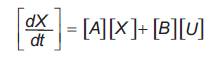
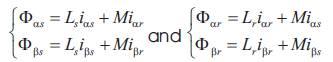
In the rotating reference frame, the dynamic model of the induction motor can be represented according to the usual d-axis and q-axis components as follows [5]-[14] :
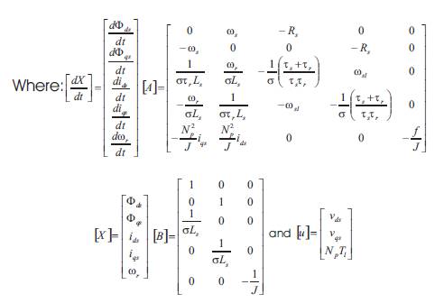
with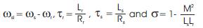
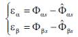
This motor model was widely used in the induction motor control design, when the current-controlled PWM inverter is employed. Generally speaking, the stator current adjustment will affect both the torque and the rotor flux. The relation between the torque and the stator current is nonlinear and this may make control design using (1) difficult. However, the vector control principle can make torque changing linearly with respect to stator currents so that the control design becomes much easier. It is well known that a decoupling control of torque and rotor or stator flux can be obtained using the vector control technique in the constant rotor or stator flux level. For perfect stator flux orientation, the stator flux linkage is aligned with the synchronously rotating -axis  and
and  We use a Pulse Wide Modulation (PWM) voltage source inverter.
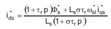
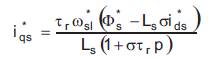
Thus, by solving (1), they obtain the d and q-axis command stator currents expressed by:
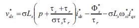
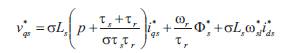
The reference d and q-axis command voltages are expressed by the following equations,
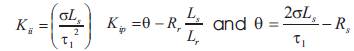
For speed controller we have designed an integral proportional (IP) speed controller in order to stabilize the speed-control loop [5]. The closed loop transfer function is given by
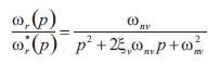
with 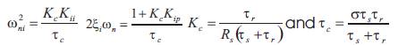 The gains of the IP controller, Kp and Ki , are determined using a design method to obtain a damping ratio of 1. The gains parameters values of the IP speed controller are:
For d- and q-axis current controller the authors used a proportional-integral (PI) controller. The closed loop transfer function is given by:
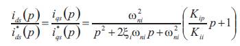
with Using the same method as speed controller, the gains Kip and Kii parameters values of the PI current controller are:
In their simulation they have used the time constant 
The general idea behind Model Reference Adaptive System (MRAS) is to create a closed loop controller with parameters that can be updated to change the response of the system. The output of the reference model is compared with an adjustable observer-based model. The error between the states of the two models is then used to drive a suitable adaptation mechanism that generates the estimate R1r for the adjustable model [5];The control parameters are updated based on this error. The goal is for the parameters to converge to ideal values that cause the plant response to match the response of the reference model.
The mathematical induction motor model, established in stationary reference frame (a,b) is given by considering ωs=0.
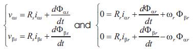
where
Substituting the rotor current and flux components in (8) by their corresponding stator one, they obtained eqn (10)
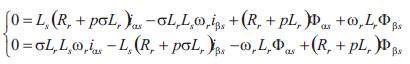
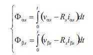
In order to identify R by use of eq. (8), they attempt to r represent the components of the stator flux vector  in terms of accessible stator variables, that is, stator currents
 and stator voltages
 For this, two independent observers are constructed. The first is derived by integrating the stator voltage equation (8) and the second is based on eq. (10) which are defined as follows:
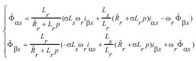
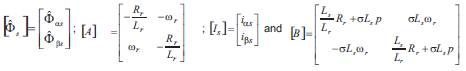
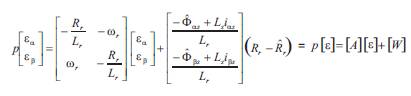
It can be seen that equation (11) does not involve the parameter Rr , this observer may be regarded as a reference model of the induction motor, and equation (12), which contain Rr , may be regarded as an adjustable model. The observer equation (12) can be rewritten by the following expression.
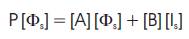
Where,
The error between the states of the two models given by eq. (14), is used to drive a suitable adaptation mechanism that generates the estimate  for the adjustable model.
The state flux error components is
Where [w] is the feedback block. The term of [w] is the input and [e] is the output of the linear forward block.
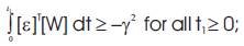
The asymptotic behavior of the adaptation mechanism is T achieved by the simplified condition limit  for any initialization. The system is hyperstable if the forward path transfer matrix is strictly positive real and the input and output of the nonlinear feedback block satisfies the Popov criterion [15]
A physical interpretation of the Popov's inequality is that the energy outputted by the non linear system is not larger than the sum of the stored and incoming energies. It can be verified that the forward path transfer function matrix H(p) given as follows,
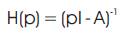
is a strictly positive real.
Considering system (15), one can easily prove that the observed rotor resistor satisfies the following adaptation laws,
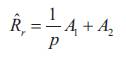
Where,
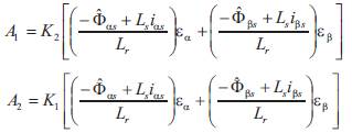
Where K1 and K2 are the positive adaptation gains by means of which the rotor speed can be adjusted.
The parameters Rr and Rr both vary with time and each may be seen as an input to the rotor equation (12). To investigate the dynamic response of the MRAS rotor resistor estimation, it is necessary to linearize the stator and rotor equations for small deviation around a working point. So, the deviations of the error ε are given by,
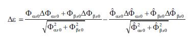
and the transfer function relating Δε to ΔR is
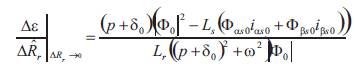
where at steady state they have 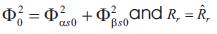 The closed loop diagram of the dynamic response of MRAS rotor resistance identification can be drawn as in Figure 1.
Where,
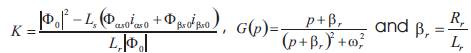
The transfer function G(p) allows two complex poles
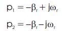
Since βr is always positive, the poles p1 and p2 have negative real parts. So G(p) stability is confirmed. The PI regulator is justified by the fact that the estimator has to perform with no error at steady state and to converge in a reasonable bandwidth compared to the dynamics speed response.
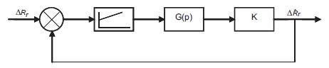
Figure 1. Closed Loop Diagram representing MRAS dynamic response
The synthesis procedure of the identifiers here considered can be briefly reviewed referring to the parallel block diagram represented in Figure 2. The block Reference model in the upper portion of Figure 2, represents the actual system having unknown parameter values. Its output is the stator flux vector. The block Adjustable Model has the same structure of the reference one, but with adjustable parameters instead of the unknown ones. This model estimates the stator flux from terminal currents and voltages and rotor resistance. Thus, the actual system can be viewed as the reference for the adjustable model.
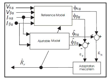
Figure 2. Structure of the Evaluation by the Adaptive Method with Model of Reference
The block Adaptation mechanism updates the unknown parameters of the adjustable system by means of the adaptation algorithms determined through the synthesis procedure. Hence, the identifier is constituted by the adjustable model, adaptation mechanism, and comparator which compute the state error as the difference between plant and adjustable model state vectors. The MRAS approach makes use of the redundancy of two machine models of different structures that estimate the same state variable on the basis of different sets of input variables.
The above presented procedure has been simulated using Matlab Software. Figure 3 shows the implemented block diagram of ISFOC induction motor drive system with rotor resistance tuning. The bloc diagram consists of an induction motor, a PWM voltage source inverter, a field orientation mechanism, a coordinate translator, and a speed controller. The gains of the IP speed controller and PI gains controller are calculated and tuned at each sampling time according to the new estimated rotor resistance. The algorithm in the field orientation mechanism needs the accurate current information thus when the error in the measured current exist the estimated in (18) does not approach the real one.
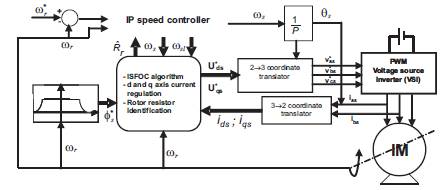
Figure 3. Block Diagram of Indirect Stator Oriented Induction Motor Drive System with Rotor Resistance Tuning
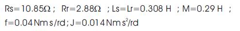
To validate the proposed method, a set of simulations, with Matlab-Simulink software package, was prepared. For simulation purposes, a typical 1kW four-pole squirrel rotor induction machine was used. The initial simulation of the vector-controlled drive was performed under various load and speed conditions and assuming all the motor variables in (13) to be constant. The sampling time for estimation and control algorithms computation is chosen as 0.2 ms. The system parameters of the induction motor drive tested in this study are given in the Appendix.
During the simulation shown in Figure 4(a), at nominal speed and a load torque, Rr was chosen to be equal to 2.88 and increased by 50% from its initial value at t = 7 s, the torque is applied with 4 Nm at t= 4s and is cancelled at t= 10s. The increasing of the rotor resistance agrees with an eventual heating of the rotor winding. The obtained result demonstrates that even if the rotor resistance changes, the proposed ISFOC procedure still gives a good estimate of this parameter.
The estimated rotor resistance, as shown in Figure 4, matches the actual rotor resistance of the machine with an error of 2% (Figure 4(b)) and so we obtain a robust control performance.
In Figure 4(c), they have seen that the rotor speeds converge to the actual value.
Also Figure 4(d) gives the actual and estimate stator flux magnitude. It has been verified that simulating the machine behaviour by using Equation (15) gives a stator field waveform that agrees quite well with the stator field observed by Equation (15).
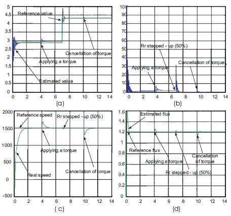
Figure 4. Identification Performance at Nominal Speed and Load Torque: (a) estimated and reference rotor resistance, (b) rotor resistance error, (c) reference and real speed, and (d) estimated and reference flux
The robustness of the adaptation algorithm to speed change is considered in Figure 5. The speed is changed from 1500 rpm to -1500 rpm at t = 4 s and from -1500 rpm to 100 rpm at t= 10 s. The two trajectories of estimated and reference rotor resistance coincide fairly well and a very good coincidence is reached. The results show that the ISFOC has a good tracking performance even when we change the speed (Figure 5 (c)).
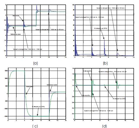
Figure 5. Estimation of rotor resistance to step change of the speed from 1500 to -1500 rpm and to 100 rpm: (a) reference and estimated rotor resistance, (b) rotor resistance error, and (c) reference and real speed.
To validate the use of the proposed procedure for induction motor resistor estimation, the simulation results have to be compared to those given by experimental tests. The experimental unit, is located at the " Research Unity of Automatic Control " (UCA). The experimental setup, is composed of a 1 kW squirrel cage motor, a drake powder, inverters, a real time controller board of dSPACE DS1104 and interfaces which allow to measure the position, the angular speed, the currents, the voltages and the torque between the tested machine and the drake powder.
The applied software are MATLAB-Simulink and Control Desk. Functions of a particular library give direct access from MATLAB script to the variables of the application program running on the dSPACE board. So, it is sufficient to develop the estimation algorithm with Simulink. The experimental stator currents, voltages and rotor resistor, observed with Control Desk, are detected at every sampling instant. The specifications and parameters of the machine are the same as those used in computer simulation.
The adaptive algorithm as described above is used to estimate the stator flux and resistance. The waveform of speed command, reference and real speed obtained are shown in Figure 6 (a) at no load. Figure 7(c) and 8(c) show the reference and real rotor speed response due to step change command from 1500 to -1500 rpm respectively from 1000 rpm to 1500 rpm. In Figure 6(a),7(a) and 8(a) they noted that the value of rotor resistance follows the reference well, and they started the machine with the actual value of rotor resistance and then to instant t = 30 s using a switcher to switch the estimated value. However, Figures 6(b), 7(b) and 8(b) show the error of the rotor resistance, which present a very low error and prove stability and convergence of the rotor resistance to the actual value for the speed 1000 rpm, 1500 rpm and - 1500 rpm.
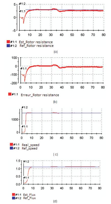
Figure 6. Identification performance at nominal speed: (a) estimated and reference rotor resistance, (b) rotor resistance error, (c) reference and real speed, and (d) estimated and reference flux
Finally, Figures 6 (d), 7 (d) and 8 (d) give the actual and estimate stator flux magnitude. They notice that there is some error due to the presence of stator resistance.
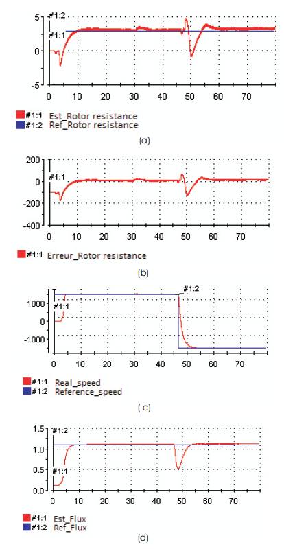
Figure 7. Estimation of rotor resistance to step change of the speed from 1500 to -1500 rpm: (a) reference and estimated rotor resistance, (b) rotor resistance error, and (c) reference and real speed.
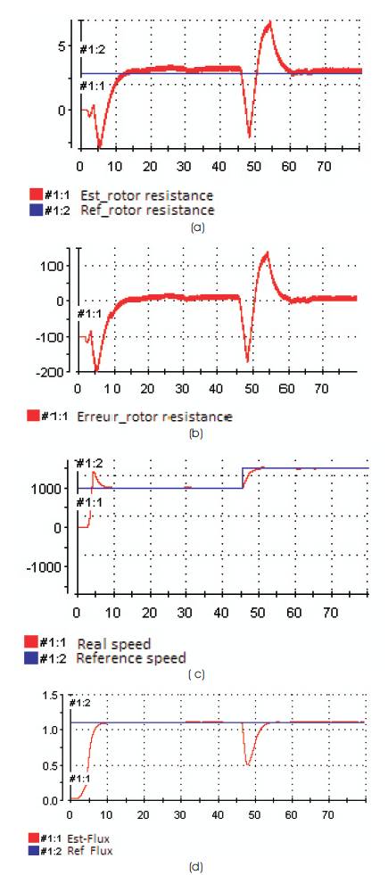
Figure 8. Estimation of rotor resistance to step change of the speed from 1000 to 1500 rpm: (a) reference and estimated rotor resistance, (b) rotor resistance error, and (c) reference and real speed.
In this paper, the authors have validated the online estimation for the rotor resistance of an induction motor operating in an indirect stator field orientated control system using the using MRAS method. The experimental results show that rotor resistance is estimated using on-line approach to be tuned during induction motor drive operation. Experimental tests have been carried out in order to validate the effectiveness of the proposed scheme. The algorithm was implemented on a dSPACE DS1104. The experiment results confirmed the theoretical algorithm of the goodness of the behaviour of the proposed method.
This technique has been applied to an indirect filed oriented induction motor control with speed sensors, but a mutual estimation of rotor resistance and speed are necessary. The solution for this problem will be shown in the next opportunity.
List of motor specification and parameters: 220 V, 1KW, 4 poles, 1430 rpm