Electromyography (EMG) is a diagnostic technique for determining the health status of the muscles and the motor neurons that regulate them. It transmits electrical signals that cause muscles to contract and relax. An EMG translates these signals into graphs or numbers and help the doctors to make diagnosis. The electric signal transmitted by the muscles will have lot of noises. Fast Fourier Transform is one of the most used algorithms for calculating the Discrete Fourier Transform (DFT). It's because of its reduction in computing time and better efficiency. A radix-2 FFT allows to analyze dynamic signals coming through muscle contractions efficiently and same can be precisely implemented using radix-4 Coordinate Rotation Digital Computer (CORDIC) algorithm. Here it deals with the calculation of muscle fatigue using EMG and proposes an ideal FFT core implementation using CORDIC algorithm as a solution for the same.
In the diagnostic procedure of Electromyography, the health status of the muscles and the motor neurons that regulate them is assessed. The motor neurons transmit electrical signals, that contract and relax muscles. An EMG translates these signals into numbers or graphs to help doctors make a diagnosis (Ali, Albarahany, & Quan, 2012).
FFT has been used in a wide range of applications. Based on Orthogonal Frequency Division Multiplexing (OFDM) (Ali, Kanagasabapathi, & Yellampalli, 2017) principle, where the system implementation is only feasible when the equipment complexity and power consumption are greatly reduced by utilizing a real-time FFT (Joseph, Rajagopal, & Karibasappa, 2012; Bansal, Dhaliwal, & Gill, 2014; Saenz, Cisneros, & Dominguez, 2015; Belabed, Jemmali, & Souani, 2018; He & Torkelson, 1996; Liu, Yu, & Wang, 2011) modulators for each individual sub-carriers.
Non-invasive electrodes and invasive electrodes record both surface EMG and intramuscular EMG signals. These days, surface detected signals are preferably used to obtain information on the time or intensity of surface activation of the muscle. Electromyography (EMG) signals are known to be most useful in both medical and engineering fields as electrophysiological signals (Nazmi, Rahman, Mazlan, Zamzuri, & Mizukawa, 2015). By recording EMG signals, the basic method for understanding the behaviors of the human body under normal and pathological conditions is provided.
Whenever an EMG signal is obtained from the muscle, it is polluted by different types of noise. It is therefore very difficult to analyze and identify the EMG signals due to the complicated pattern of the EMG, especially when EMG movement occurs. To solve this problem, the signal must be processed using DFT before being sent to storage.
Fast Fourier Transform can be used for signal analysis in the surface electromyography. A radix-2 FFT allows to analyze dynamic signals coming through muscle contractions efficiently and same can be precisely implemented using radix-4 CORDIC algorithm.
Due to the pattern of the EMG, particularly when EMG movement occurs, it is therefore very difficult to analyze and classify the EMG signals. Fast Fourier Transform is the most efficient method for the same to solve this problem, the signal must be processed using DFT before being sent to space. Liu et al. (2011) explains an efficient one-way commutator-feedback (SDC-SDF) radix-2 pipeline fast Fourier transform architecture that includes log2 N-1 SDC stages and 1 SDF stage. However better efficiency achieved in higher frequency than in lower frequency. In lower frequency hardware utilization is lesser than the proposed.
In Wold and Despain (1984) special attention is given in proposition for implementing high performance FFT using VLSI. In view of these constraints, VLSI implementations have constraints that vary from those of discrete implementations, prompting another look at some of the standard FFT's algorithms. The parallel pipe lined architecture of the processor also has higher and it has throughput with lowered power consumption (Kannan & Srivatsa, 2007).
In Han, Erdogan, Arslan, and Hasan (2005) importance is given for low power consumption, which can be gained by combining hybrid algorithms for low power and architectures. However improvement is needed in the comparative study conducted for different FFT processor in ideal conditions and the real time results varies.
Zhou, Peng, and Hwang (2009) emphasizes that an efficient mapping of the Single-path Delay Feedback (SDF) pipeline and Fast Fourier Transform (FFT) architecture to Field-Programmable Gate Arrays (FPGAs) is proposed. Improvement is required as there is no significant explanation on architectural or algorithmic choices for increasing the throughput.
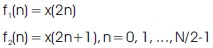
Rani, Sarma and Prasad (2012) have discussed the Radix- 2 FFT algorithm by considering the calculation of the N = 2v point DFT by the divide-and conquer approach. The authors have split the N-point data sequence into two N/2- point data sequences f1 (n) and f2 (n), corresponding to the even-numbered and odd-numbered samples of x(n), respectively, that is,
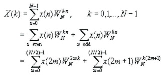
Thus f1(n) and f2(n) are obtained by decimating x(n) by a factor of 2, and hence the resulting FFT algorithm is called a decimation-in-time algorithm. Now the N-point DFT can be expressed in terms of the DFT's of the decimated sequences as follows:
But W2N =WN/2 . By substituting, the equation can be expressed as,
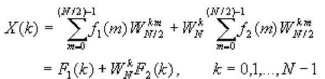
where F1(k) and F2(k) are the N/2-point DFTs of the sequences f1(m) and f2(m), respectively. Since F1(k) and F2(k) are periodic, with period N/2, F1(k+N/2) = F1(k) and F2(k+N/2)=F2(k).
In addition, the factor WNk+N/2 = -Wnk.
Hence the equation may be expressed as,
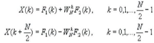
Here it observes that the direct computation of F1(k) requires (N/2)2 complex multiplications. The same applies to the computation of F2(k). Furthermore, there are N/2 additional complex multiplications required to compute WNkF2(k). Hence the computation of X(k) requires 2(N/2)2 + N/2 = N2/2 + N/2 complex multiplications. This first step results in a reduction of the number of multiplications from N2 to N2/2 + N/2, which is about a factor of 2 for N large. The decimation of the data sequence can be repeated and again until the resulting sequences are reduced to onev point sequences. For N = 2v, this decimation can be performed v = log2N times. Thus the total number of complex multiplications is reduced to (N/2)log2N. The number of complex additions is Nlog N (Rani, Sarma, & 2 Prasad, 2012). As shown in Figure 1, the Architecture implemented is Radix-2 Single path Delay Feedback (RSSDF). By storing the butterfly output in feedback shift registers, this architecture uses the registers more effectively. At each point, as shown in Figure 2, a single data stream passes through the multiplier. It has the same number of butterfly units and multipliers as in the R2MDC method, but the memory limit is much lower: N-1 registers (He & Torkelson, 1996) FFT can be decomposed using a first half/second-half approach that divides the output sequence X(r) into increasingly smaller subsequence; this procedure is called decimation-in-frequency (DIF) FFT.
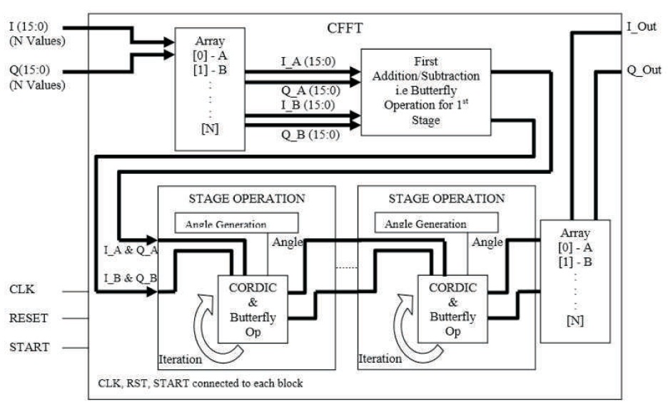
Figure 1. Over All Block for N Point FFT
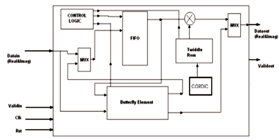
Figure 2. Internal Architecture of Each Stage of FFT
The butterfly starts storing the data into FIFO when valid in is high. Butterfly has an internal control logic which consists of three states. In first stage it receives real and imaginary data and stores it into FIFO till it is full. Once the buffer is full it will go to next state. In this state it reads data from FIFO as well as receives input data, processes these two inputs and generates two outputs. In second state the addition and subtraction of inputs will be performed, subtraction results of inputs are stored in FIFO and addition results are sent to next stage. Depending on stage after receiving entire input data state is incremented to next state i.e. third state. In this state the subtraction results stored in the FIFO in previous state are sent to next state.
If valid in is high the received data is stored in the FIFO again. The output data bits i.e. Data out (Real and Imaginary values) are connected to the inputs of the next stages and the valid out output signal acts as valid in input to the next stage. This is how all the 10 stages are connected to form a complete 1024 Point FFT. This Architecture is entirely scalable to tune to any size FFT. If the 1st stage is removed then it becomes a 512 point FFT. And if 2nd stage is removed it becomes a256 point FFT.
CORDIC (COordinate Rotation DIgital Computer), also known as Volder's algorithm, is a simple and efficient algorithm for calculating hyperbolic and trigonometric functions, usually converging by iteration to one digit (or bit) (Tang, Yu, Han, & Zhang, 2016). CORDIC is a bit by bit algorithm. CORDIC is used when no hardware multiplier is available (e.g. in simple microcontrollers and FPGAs). It requires only basic shift and add operations.
It calculates the trigonometric functions of sine, cosine, magnitude and phase (arctangent) to any desired precision CORDIC's idea is to "rotate" the phase of a complex number by multiplying it by a succession of constant values. (CORDIC FAQ, n.d).
However, the multipliers can all be powers of 2, so they can be done with just shifts and adds in binary arithmetic; no actual multiplier is required. There are two inputs real input and imaginary input. The inputs are stored in an array. The 8-point FFT is generated using series of adder and multiplier. CORDIC is used in the multiplier section where the authors use stage level operation for the same.
Step 1: If valid = '1'; start receiving data and store in FIFO until it is full. Then check for FIFO. If FIFO='1', go to step 2.
Step 2: Read and process data from FIFO. Then the output and subtraction result stored into FIFO. The addition result send out as output.
Step 3: Stage incremented to next stage.
Step 4: Read data from FIFO then multiply with twiddle factor and send data to output.
Step 5: If valid = '1', stores the input data.
Step 6: If validout ='1', indication of output data is valid.
The simulations results for 8 point, FFT, are discussed in the following sections.
4.1.1 8 Point FFT Simulations
Figure 3 shows that, when valid in is kept high and real in and image in inputs are given. As a result valid out goes high and gives real data out and image data out.
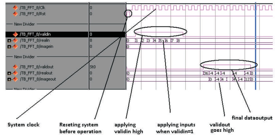
Figure 3. Simulation Result
4.2 8 Point FFT Verilog MATLAB Comparison
Figure 4 shows the MATLAB result obtained, which is used for comparison with the verilog result to ensure the output matches.
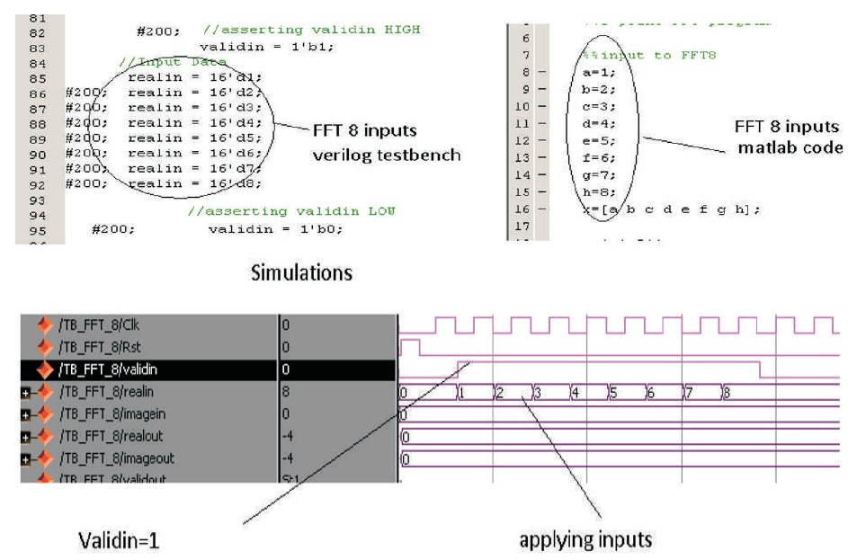
Figure 4. MATLAB Result
Figure 5 shows the Verilog output for 8 point FFT matching with 8 point. MATLAB simulation output for FFT. Hence confirming the output obtained.
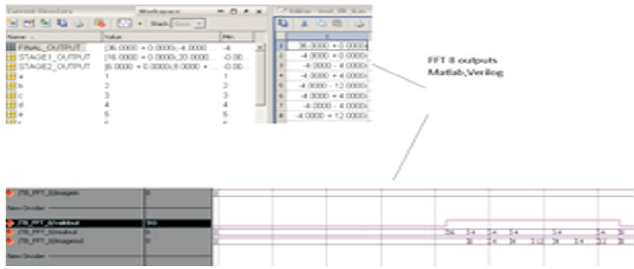
Figure 5. Verilog Output for 8 Point FFT Matching with 8 Point
Figure 6 shows the Stage 1 output comparison between Verilog and MATLAB hence confirming the output.
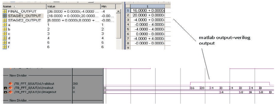
Figure 6. Stage1 Output Comparison between Verilog and MATLAB
Figure 7 shows the stage 2 output comparison between Verilog and MATLAB to ensure the output matching.
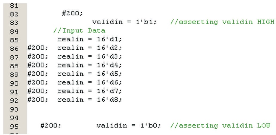
Figure 7. Stage 2 Output Comparison: Verilog and MATLAB
4.3.1 FFT 1024 Simulations Results
The result is verified for 8 point FFT. As it works for 8 point FFT it also works for 16, 32, 64…1024 because it is the basic building block of this architecture and it remains same for all stages.
In order to verify for 1024 point, here it generated 2 frequencies i.e. 50 Hz and 120 Hz, added up the two signals. It now acts as the input to 1024 point FFT. In Frequency domain view, the expected plot output for FFT should get the peaks at 50 Hz and 120 Hz on the graph. Here it plotted both MATLAB and Verilog output plot and can conclude that the output matches. There is a loss of precision and noise in Verilog output because here it uses 16 point decimal format as compared to MATLAB which uses 64 bit IEEE floating point format, hence accuracy get reduced. It is clear that the peaks at the correct frequency confirming the working of the coding done.
The Figure 8 shows the simulation results of 1024, Figure 9 shows the input signal plot and Figure 10 shows the Input signal generated from MATLAB given as input signal to Xilinx.
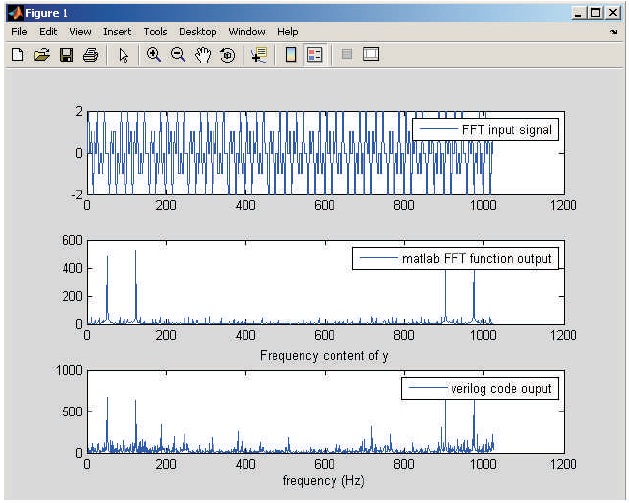
Figure 8. Simulation Results of 1024
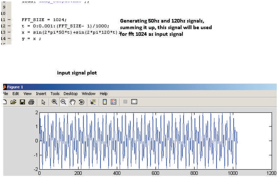
Figure 9. Input Signal Plot
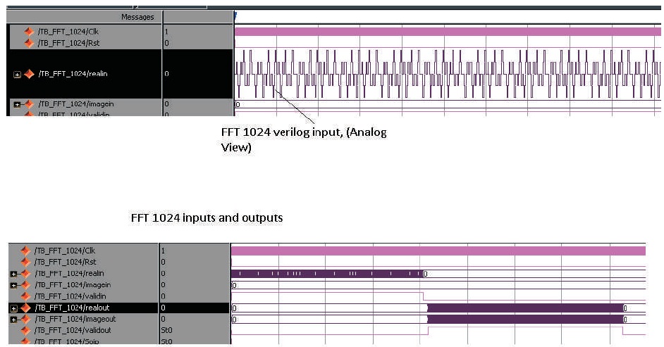
Figure 10. Input Signal Generated from MATLAB given as Input Signal to Xilinx
When valid in is kept high and real in and image in inputs are given. Valid out goes high and get real data out and image data out.
The biggest concern in using EMG is the noise generated, which corrupts the electric signal generated by the muscles. The project explains an efficient FFT core for filtering the electric signals for Electromyography. This project introduces the concept of using CORDIC in generating the FFT for filtering the electric signals. Though the system presented here is efficient but has its own limitations. The current approach can be improved by using radix 4 FFT as radix-4 completes one cycle for a given waveform hence performance is improved. Also the biggest concern with this approach is it is efficient for static signals but when try to measure dynamic signals like running then the efficiency of radix -2 is lesser compared to radix-4. As an enhancement the authors suggest to use radix-4 FFT for creating the FFT core. The performance can be improved tremendously going for wavelet form for building the FFT signal. Another enhancement that can be added is passing a 3-D image instead of 2-D signal for calculating the EMG.