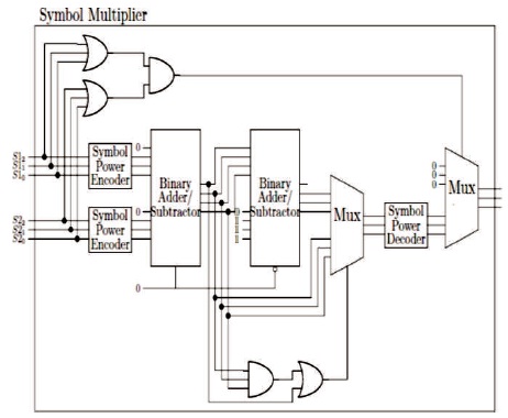
Figure 1. Reed Solomon Symbol Hardware Multiplier
Very Large Scale Integration (VLSI) is the science of integrating millions of transistors in a silicon chip. It is a term describing semiconductor integrated circuits composed of thousands of logic elements of memory cells. Error that occurs during the write and read operations in memory cells is a drawback for the memory ICs. Error detection and error correction plays a vital role in VLSI design by increasing the accuracy and performance of the desired circuits. Depending on the properties of the system, the channel coding can use either Automatic Repeat Request or Forward Error Correction technique in which the error correcting is introduced. In this work two techniques are used i.e. Reed Solomon code and Bose–Chaudhuri–Hocquenghem (BCH) code, where Reed Solomon code is a error detection technique which is mainly used for its possibility to adjust block length and symbol size. BCH code is a error correction technique, it is used because of its easy implementation. These two techniques are implemented in the memory cells and the performance metrics such as block length, minimum distance are calculated. From the VHDL simulation result, it is proved that BCH code is better than Reed Solomon code for the memory cells of the ICs.
In digital communication system through a channel from the source to a user destination. information bearing signal is passed. Digital communication system process the information signal to form discrete messages, which makes the information more reliable for transmission. Channel coding is an important signal processing operation for the efficient transmission of digital information over the channel capacity for important parameter for error free transmission. An efficient digital communication system faces the task of providing a system, which is cost effective and gives the user a level of reliability. The information transmitted through the channel to the receiver is prone to errors. These errors could be controlled by using Error-Control coding, which provides a reliable transmission of data through the channel. In this paper, a few error control coding techniques are discussed that rely on systematic addition of redundant symbols to the transmitted information. Two basic objectives at the receiver end are Error Detection and Error Correction. Error correction codes are required to increase the reliability of binary transmission or storage system. To have a reliable communication through noisy medium that has an unacceptable bit error rate (BER) and low signal to noise ratio (SNR), Error correction has to be done by adding parity bits to the original message bits during transmission of the data. Error correcting codes have a wide range of applications in different fields like digital data communications, memory system design, and fault tolerant computer design among others. Error detection is the detection of errors caused by noise or other impairments during transmission from the transmitter to the receiver (Mohammed, 2013). It uses the concept of redundancy, which means adding of extra bits for detecting errors at the destination. In error correction the receiver can use any of the error-correcting code, which can automatically corrects certain errors and enables reconstruction of the original data.
Kumar and Gupta (2011) made an analysis by applying the binary phase shift keying modulation scheme in symmetric additive white Gaussian noise using Reed Solomon code for correcting burst errors. Channel coding for error detection and correction helps for communication to reduce the effects of noisy channel. Bit error rate performance improves the code rate and decreases to improve large block lengths constant and it's easier and simple to understand. The simulation result apply the bit error rate performance of lower Signal-to- Noise Ratio (SNR). Lone, Puri, and Kumar (2013) in their paper, discussed the performance of analysis of various forward error correction techniques. Bit error rate improves the code size(n) which increases the constant code rate and similar error correcting capability (t). The multiple error can be detected and corrected using BCH code. Al Azad and Shahed (2014). presented a compact and fast hardware implementation technique of Reed Solomon Encoding and Decoding algorithm. Reed Solomon codes are very efficient for the detection and correction of burst errors. Reed-Solomon (RS) codes are based on the finite fields so they can be extended or shortened. Reed Solomon codes provide a wide range of code values that can be chosen to optimize performance.
Sahana and Anandi (2015) presented the simulation of BCH encoder and syndrome computation where 215 message bits are encoded into a 255 bit codeword. If there is any 5 bit error in any position of 255 bit codeword, it can be detected and the encoder is implemented using Linear-Feedback Shift Register (LFSR). BCH code forms a large class of powerful random error correcting cyclic codes and the reliability is very simple to encode and decode. The compact and Field-Programmable Gate Array (FPGA) were used for functional verification and to avoid the data corruption, error correction codes are widely used to protect storage devices to improve communication systems. The main objective is to decrease latency multiple error detection and correction in data signal for decreasing the power consumption and increase the performance. Both correction and detection techniques are used for reliable comto munication over a noisy channel. Kapoor and Khare (2017) analyzed the performance of Reed Solomon and BCH code for different modulation scheme for additive white Gaussian noise channel. When the bandwidth is constant the signal to noise ratio increases and BCH can be improved for the given bandwidth by taking the smaller code rate. The burst error correction of reed Solomon code is better than the BCH code. Survey of all these paper explains about the bit error rate, optimum performance, power consumption and bandwidth wide range of applications in digital communication.
Reed Solomon code is an error detection code which can be operated on the information by dividing the message stream into the block codes. The generator polynomials generate and its encoder redundant symbols are appended to the message symbols. In decoder, error location and magnitude are calculated using the same generator polynomial. And the correction is applied on the received code symbols by using the theory of finite fields. RS codes are one of the most powerful burst error correcting codes and have the highest code rate of all binary codes, a symbol may have all its bits in error, this counts as only one symbol error in terms of the correction capacity of the code. The (n,k) code is used to encode m-bit symbols.
Block length, n=2m-1 symbols, Message size k symbols, Parity check size n-k=2t, Minimum distance, dmin = (2t+1). A finite field in which the finite order explicit the number of elements is called a Galois field in the order of finite field is always a prime or a power of prime. For each prime power one finite field GF (pm) exists where p is prime number and m is a positive integer. A field is said to be infinite and it consists of infinite number of elements and all the finite field contain a zero element and an element called generator or primitive element alpha such that every nonzero element in the field can be expressed as a power of this element. Encoders and decoders for linear block codes over GF(2m) such as Reed Solomon codes require arithmetic operations in GF(2m). In addition, decoders for some codes over GF(2m) requires computations in extensions fields GF(2m) and addition and subtraction are simply bitwise exclusive OR. Numerous approaches can be used to perform multiplication as well as bit serial, bit parallel combinational, and software. Division requires the reciprocal of the divisor, which can be computed using several methods in hardware, including Euclid’s algorithm, lookup tables. Combinational circuits for Galois field arithmetic are straightforward except for division (Proposed Reed-Solomon Encoder and Decoder, n.d).
In Reed Solomon Code the whole system may be represented as a junction of separate blocks together that will operate synchronously using a universal clock signal. The system starts by receiving the message that is encoded using a reed Solomon code (7, 5): 7 number of codeword and 5 number of message symbols. The encoders has the function of generating parity symbols such that output codeword is not affected by single symbol errors while travelling through the channel. The (7, 5) Reed Solomon symbol hardware multiplier is shown in Figure 1.
Figure 1. Reed Solomon Symbol Hardware Multiplier
The input system of each symbol should pass through a symbol power encoder as shown in the Figure 1. This encoder will map each symbol power into its equivalent decimal. This mapping process is much smaller than the one required mapping all multiplication possibilities between 3 bit symbols. This mapping only maps 7 different patterns a table is used to map 64 different patterns of full multiplier encoder. As in algebra in order to multiply both symbols the powers can be added. The Binary Adder/ Substractor unit take the output of each symbol power encoder and add them together using a standard binary adder. As the maximum value of each power is 6, the sum of the symbols would never be greater than 12, which in binary can be represented using 4 bits. Hence the binary adder would take 8 inputs and return 4 outputs. The Adder and Subtractor are in the same block and the operation performed by the adder/ substractor unit is controlled by logic variable. Multiplexer is used to select one of the outputs. It is used to select the three least significant bits since those are the bits that have the information about the symbol power, which has to be decoded. This multiplexer will select the subtractor signal if the result of the adder is either 0111 or if the most significant bit is high, which means the addition was greater than seven. The output of the Multiplexer is then send to a Signal Power Decoder, that uses the reverse encoder logic. The system will not consider the zero symbols because zero cannot be represented as a power of a number. Although just as in algebra when a BCH code is a ‘t-error’ correcting code in that it can detect and correct up to t-random errors per code word. The Hamming single error correcting codes can be described as BCH codes. The BCH codes offer flexibility in the choice of code symbol is multiplied by zero the output should be zero and a final multiplexer should select either zero or the output of the symbol power decoder for the output of the system. If either of the input symbols is zero then this multiplexer will select zero as the output, but if both of them have at least one bit not equal to zero then the output will be given by the output of the decoder.
Reed Solomon code are error correcting codes that have found wide ranging applications throughout the field of digital communication and storage devices, wireless communication, digital television, deep space satellite communication networks. The error correcting codes will become more efficient or improves the error performance.
BCH abbreviation stands for the discoverers, Bose and Ray - Chaudhuri (1960) and independently Hocquenghem (1959). BCH codes are cyclic codes which is a subclass of linear block codes, when it obeys the cyclic property. Cyclic code form a subclass of linear block codes. This class of codes is a remarkable generalization of the Hamming codes for multiple error correction. The most common binary BCH codes are characterized for any positive integers (m) equal to or greater than 3 and the number of errors can be detected and corrected (t) by the following parameters:
Block length: n = 2m – 1
Number of message bits: k ≥ n – mt
Minimum distance: dmin ≥ 2t + 1
Each BCH code is a t-error correcting code in that it can detect and correct up to t random errors per code word. The Hamming single error correcting codes can be described as BCH codes. The BCH codes offer flexibility in the choice of code parameters, namely, block length and code rate (Sahana & Anandi, 2015).
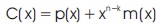
An (n,k) binary BCH code converts k-bits message into n-bits code word. The message vector can be expressed in a polynomial form as

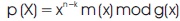
The message digits are utilized as a part of the code word. The systematic encoding can be implemented by
Where p(X) is the reminder and can be expressed as
Suppose that a code word c(x) =C0+ C1x + C2x2 +...+ Cn−1Xn−1 is transmitted and the transmission errors result in the following received vector
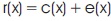
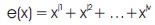
where e(x) is the error pattern.
Suppose that the error pattern e(x) has v errors at locations Xj1, Xj2,… ,Xjv, that is,
Where,

It follows from the definition of a t-error-correcting BCH code of length n=2m−1 that each code polynomial has α,1, 2,… , α2 t as roots, c(αi) =0, for (1≤ I≤2 t).
The block diagram of BCH code is shown in Figure 2. The syndrome generator calculates syndromes, and the calculator computes modified syndrome polynomial S(x). The equation checker checks whether deg (e(x)) is reduced or not. In the original step-by-step decoding algorithm, it should compute at most 2n iterations causing a long decoding latency, and it is obviously not suitable for high-speed NOR flash memories. The message digits are utilized as a part of the code word. The message digits are shifted into the rightmost k stages of a code word register, is shifted and then appending the parity digits by placing them in the leftmost n-k stages. For the BCH circuit, a control signal is needed to allow the data signal to enter the encoding circuit and pass the output at the same time. Control signal gives a delay in order to make the encoding circuit able to prepare the parity bits (Mohammed & Abdulsada, 2013).
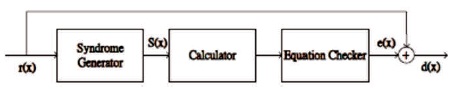
Figure 2. Block Diagram of BCH Code
Simple logic diagram hardware BCH having the parallel in serial out shifter register and the message digits are utilized as a part of the code word. The BCH code logic circuit shown in Figure 3 have shifted the message digits into the rightmost k stages of a codeword register, and then appending the parity digits by placing them in the leftmost n-k stages. The input data of the encoding circuit is 7 bits and the output is a serial of 5 bits. For the BCH circuit, a control signal is needed to allow the data signal to enter the encoding circuit and pass to the output at the same time. Also control signal gives a delay in order to make the encoding circuit able to prepare the parity bits. As a result the control signal is necessary to control the operation of switch 1 and switch 2. When all the syndrome components are zero, this means that there is no error introduced for the transmitted code word during the transmission through a communication channel and hence the received data is the same as the transmitted data. A BCH code is a polynomial code that operates over Galois fields or finite field so that the computation processes of a BCH error correcting code such as addition, subtraction, multiplication, and division are designed to operate over finite fields. The error location polynomial coefficients of (7,5) BCH code are computed. The multiplication circuit which multiplies two elements over Galois fields GF(2m) for m=4 is needed in computations of error location polynomial coefficients.
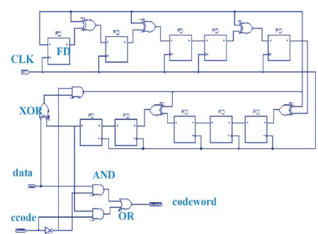
Figure 3. BCH Logic Circuit Hardware Implementation (Mohammed & Abdulsada, 2013)
In the Reed Solomon code, each symbol should pass through a symbol power encoder and this encoder will map each symbol power into equivalent decimal, and then the binary adder/subtractor unit take the output of each symbol power and add them together using a standard binary adder and controlled by logic variable. Multiplexer is used to select one of the outputs. And the output of the multiplexer is send to a signal power decoder, that uses the reverse encoder logic where parity bits get added and transmitted over a channel and the sample binary message are transmitted by the system and message can be mapped as symbol. After passing through the encoder the code word was generated and transmitted through the binary adder, which has generated some error code word that holds its value by passing through the multiplexer and the output symbol error is detected and corrected only at a time as shown in Figure 4.
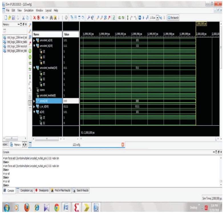
Figure 4. Simulation Result for Reed Solomon Code
From the BCH circuit, a signal is needed to allow the data signal to enter the encoding circuit and pass the output at the same time. It offers flexibility to select code parameters namely block length and code rate and the error location polynomial coefficients of BCH code are computed. The input is given and for each BCH code a terror correcting code is assigned which can detect and correct up to (t) random errors per code word and the clock frequency is reduced at the particular time as shown in Figure 5.

Figure 5. Simulation Result for BCH Code
In the Reed Solomon code the graph is drawn from the (n,k) and the block length and minimum distance are compared for the parity check size and message bits. This is greater than the code word and the size is always maximum as shown in Figure 6.
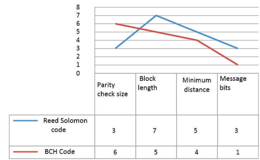
Figure 6. Comparison of BCH and Reed Solomon Code based on Performance Parameters
In BCH Code, high calculation rate using parallelization implementation is very fast and it’s easy to modify. But in Reed Solomon code circuit implementation is easy at low cost, while it can detect and correct only one error at a time. In BCH code, it can detect more than one error at particular time. These two techniques are implemented in the memory cells and the performance metrics such as block length and minimum distance are calculated. From the simulation result, it is proved that the BCH Code is better than the Reed Solomon code.