
Figure 1. Basic Multiplication Operation
This paper presents the design and implementation of Modified Booths encoding algorithm with enhanced speed. Multiplication is the most commonly used operation in every step of arithmetic. The speed of multiplier determines the speed of processor. So, there is a need for high speed multiplier. Adders play a dominant role in arithmetic addition of partial products. Increase in the speed of any arithmetic operation results in the increase of speed of overall operation of multiplier. So the main focus in this paper is to increase the speed of adder in turn increasing the speed of multiplication process. An algorithm is proposed using Modified Booths algorithm, Wallace tree structure, and Kogge-Stone adder design. MBE reduces the number of partial products and has least latency compared to other multiplier algorithms. Wallace tree structure increases the speed of accumulation of partial products. A Kogge-Stone adder design is used in the multiplier design, which yields to reduced delay and area. The proposed Modified Booth Multiplier design shows better performance compared to that of the conventional method using Kogge-Stone Adder and has advantages of reduced area overhead and critical path delay. The proposed design has been synthesized using Xilinx ISE 14.2 design tool using Verilog HDL.
Multiplication is termed as repeated addition. In decimal system, the multiplication of numbers is carried out by multiplying the multiplicand by one bit of the multiplier at a time and the resulting partial product for each bit is placed in such a manner that the LSB is under the corresponding multiplier bit. In case of binary multiplication, there are certain advantages. Multiplication is actually the addition of multiplicand with itself after some suitable shift depending upon multiplier bits. Thus, multiplication is the process of shifting and adding. This process is to be continued until the shifting due to MSB of the multiplier is done and final addition is made. But it takes huge hardware resources and simulation takes very large time for the final output. High speed Modified Booths and parallel multipliers (Trivedi, Nayak, & Vayada, 2015) are used in DSP applications.
In VLSI field, design of any multiplier should yield an increase in speed and reduction in area, power consumption, and delay. Multiplication operation involves three processes.
In partial product generation stage, Modified Booths encoding algorithm (Seo & Kim, 2009) is used to generate as well as reduce the number of partial products. MBE algorithm reduces the number of partial products to half. If the operand is of n bits, the number of partial products is n reduced by a factor of 2nd. The basic multiplication operation is shown in Figure 1.
Figure 1. Basic Multiplication Operation
In this paper, the main focus is to improve the computation speed of multiplier by designing high speed and area efficient adder. A modified Booths encoding multiplier is designed using high speed Kogge-Stone adder. Also the existing model adder is compared with the proposed MBE design with Kogge-Stone adder in terms of speed, area (number of LUTs utilised), and power consumption.
In adders like Ripple Carry adder, propagation delay is more which is the major factor that limits the speed of multiplication. Each full adder waits for the carry bit from the previous full adder output in the design, thereby increases delay with the number of stages.
Here is an alternate design which includes Carry Look ahead adder. CLA improves the speed of calculation by reducing the amount of time required to determine carry bits. The delay or wait time is reduced by determining the carry bits before the sum. Two concepts are used to generate carries, namely Carry Generate and Carry Propagate bits. The n-bit CLA accepts n bit signals P[n-1:0] G[n-1:0] and Cin thereby produces n+1 carries [n+1]C. The block diagram of carry look ahead adder is as shown in Figure 2.

Figure 2. Block Diagram of Carry Look Ahead Adder
Firstly, Propagate and Generate bits are determined using the formulae mentioned below.


The carry is generated simultaneously using the formula given below.

Kogge-Stone adder is a Prefix adder which is a form of Carry Look ahead adder. Carry is generated with less delay compared to that of other adders. The high speed adder circuit is designed considering the advantages of both Prefix adder and Carry Look ahead adder. Carry is generated in O(logn) time. It is considered as the adder with less delay and hence used for high performance arithmetic computations (Kang & Gaudiot, 2006). The schematic diagram of Kogge_stone adder is as shown in Figure 3. Figure 4 shows the block diagram of proposed algorithm
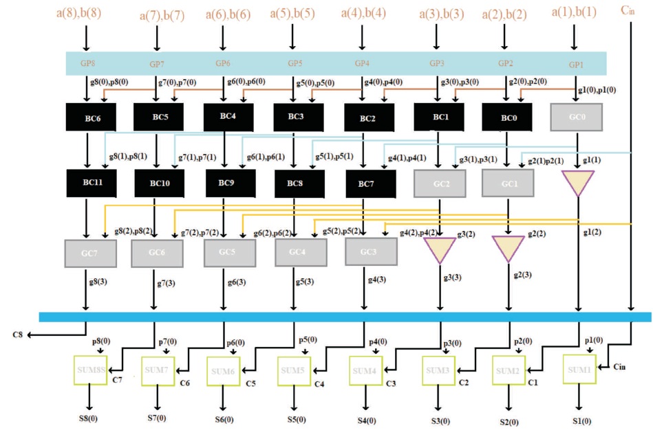
Figure 3. Schematic Diagram of Kogge-Stone Adder

Figure 4. Block Diagram of Proposed Algorithm
The functionality of KSA is analyzed in the following subsections.
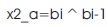
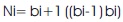
Here, it determines the Propagate and Generate bits corresponding to each pair of bits in both the operands. The expressions are given below.


This involves computation (Mitra & Bakshi, 2015) of carries corresponding to each bit. It uses group Propagate and group Generate bits as intermediate stages, which are determined using the following expression.
This is the final step of addition where the sum bits are determined. The expression for final sum is given below.
Booth's algorithm is a method of multiplying two binary operands in 2's complement notation. Here, multiplication is performed with repeated addition operations by following Booths encoding algorithm.
Modified Booths encoding algorithm (Kaur & Bansal, 2011) involves three major steps, namely recoding the multiplier bits, reducing the number of partial products, and addition that gives the final product.
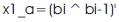
Radix-4 Booth encoding algorithm is used here which increases the speed of multiplier and reduces the area of multiplier circuit. In this algorithm, every second column is multiplied by 0 or +1 or +2 or -1 or -2 instead of multiplying with 0 or 1 after shifting and adding of every column of booths multiplier. Thus, half of the partial products can be reduced using MBE algorithm. Table 1 shows the SUMBE operation.
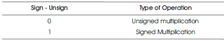
Table 1. SUMBE Operation
Sign bit (Rajput & Swamy, 2012) is used to differentiate the positive operands from negative operands and it is indicated by active low. Figure 5 shows the block diagram of Booth Encoder.
Figure 5. Block Diagram of Booth Encoder
The Table 2 below shows the functional operation of Radix-4 MBE which consists of 8 different states.
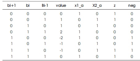
Table 2. MBE Algorithm

The booth decoder gets input signals from the booth encoder. Based on these signals, the decoder produces the partial products. These signals will indicate the operation to be performed by the decoder on the multiplicand in order to produce the partial product. Figure 6 shows the block diagram of Booth Decoder.
Wallace tree structure reduces the number of partial products to two by layers of full and half adders. Modified Booths and Wallace tree structure (Bano, 2012) are the best techniques for high speed multiplication. It has the best performance, but results in complication to implement for more number of input bits. For performing fast addition operation, Wallace tree structure is widely used. The delay of the overall operation will be O(n), which will be further reduced to O(log3/2n).
In this paper, the implementation and analysis of proposed Modified Booths Encoding algorithm is done. The results of proposed model are compared with that of the existing design. The designs are simulated using Xilinx ISE 14.2 design tool using Verilog HDL. Based on synthesis report generated, delay obtained and area in terms of number of LUTs utilised are determined.

Figure 6. Block diagram of Booth Decoder

Table 3. Existing Model of MBE (Parmar & Singh, 2013)
The proposed architecture (Saxena, Purohit, & Joshi, 2013) is compared with that of existing model in Table 3. A delay of 19.262 ns is achieved while the same in the previous work resulted in 28.172 ns. This improvement is mainly due to the use of Kogge-Stone adder. Figures 7-9 shows the simulation results.

Figure 7. Simulation Result 1

Figure 8. Simulation Result 2

Figure 9. Simulation Result 3
For input X = 9 and Y = 9, output is binary equivalent of 81.
Case A shows the simulation result of signed and unsigned numbers in binary. Here, the 8–bit operands are considered as signed numbers and the product of 00001001 X 00001001 is 0000000001010001.
For input Y = 7 and X = 9, output is binary equivalent of 63.
Case B shows the simulation result of signed and unsigned numbers in binary. Here, the 8–bit operands are considered as signed numbers and the product of 00000111 X 00001001 is 0000000000111111.
For input Y = 9 and X = 7, output is binary equivalent of 63.
Case C shows the simulation result of signed and unsigned numbers in binary. Here, the 8-bit operands are considered as signed numbers and the product of 00001001 X 00000111 is 0000000000111111.
The proposed architecture is compared (Saini, Agarwal, & Kansal, 2015) with the existing Modified Booth multiplier in Table 2. A delay has been achieved for 8-bit multiplication as 19.262 ns and for 16-bit multiplication as 20.275 ns. While the same in the previous work was 28.172 ns, which means that we designed a high speed Modified Booth multiplier. This improvement is mainly because of Kogge-Stone adder.
Table 4 illustrates that the proposed model is applicable for both signed and unsigned operation and here AMBE is used to implement the 8-bit and 16-bit multipliers.

Table 4. Proposed Model of MBE
Table 5 shows the comparison of proposed model of 8-bit and 16-bit signed and unsigned multipliers in terms of percentage performance computation. It can be clearly identified that the performance of proposed model is far better when compared with existing model.
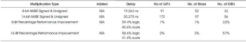
Table 5. Percentage Performance Improvement Computation of AMBE
Every multiplier will depends on the number of inputs is proportional to size of the algorithm. A comparative study of Existing and proposed model is given in Table 6.
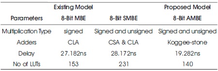
Table 6. Comparative Study
The comparative study of existing models and proposed model is given in Table 6. The proposed model owns advantages when compared to the existing models. The proposed algorithm is valid for both signed and unsigned multiplication. The delay is reduced to 19.282 ns in the proposed model. The area is also reduced.
The RTL schematic for the proposed MBE model is shown in Figures 10 and 11.

Figure 10. RTL Schematic of MBE
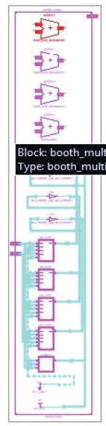
Figure 11. Detailed RTL Schematic of MBE
In this paper, Advanced Modified Booths multiplier with high speed adder is proposed. In the final stage of addition, Kogge-Stone adder is used instead of Carry Look ahead adder which improved computational speed, reduced power consumption and area.
Delay, power consumption, and area can be further reduced. As the number of bits increases, the size of algorithm increases. This proposed model can be implemented for 32-bit and 64-bit but there may be complexity in design.