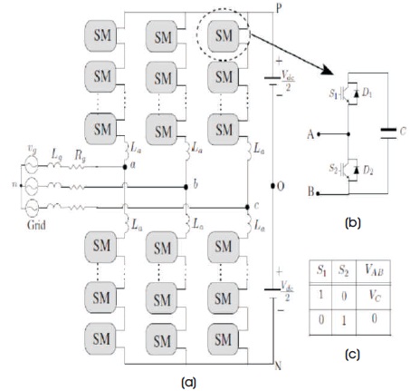
Figure 1. Schematic Representation of MMC: (a) Topology, (b) Sub-module, (c) Switching States (Purkait & Pandey, 2018)
With new developments in semiconductor technology, automation and control systems are booming. These sources have not only reduced the system size, but also allowed it to perform tasks that were impossible a few years back. Designing a DC-DC converter has always been a challenge, i.e, the way it should perform the conversion either unidirectional or bidirectional, compactness, power flow control, generation of a wide range of output levels, reduction in switching losses, etc. Among different DC-DC converters available, there is more scope for new topologies in multilevel converters. A unique multilevel converter that having striking features like high scalability, modular nature, internal fault cutback, regulation of voltage, and smaller space requirements is Modular Multilevel Converters (MMC). This paper sets an outline for studying Modular Multilevel Converters (MMC) to be applied and further developed for the wide range of applications. The later sections involve their fundamentals, modeling, control modulation, and some of the implemented applications.
Modular Multilevel Converters (MMC) is leading the region of DC-DC converters. Compared with two-level converters, MMC has greater advantages. Its specialization in high power and high voltage has made it one of the most competitive solutions for voltage source converter applications (Lai & Peng, 1996; Rosas-Caro et al., 2010). This topology is very flexible and suitable and has been modified time and again for all kinds of HVDC (High Voltage Direct Current) application. The model simply relies on redundant sub-modules, low filter expense, lesser semiconductor losses, and common mode voltages (Son et al., 2012). MMC was invented by Lesnicar and Marquardt (2003). Over the years, MMC has become most researched areas in terms of power transmission, modular nature, transformer-less operation, extraordinary performance, good efficiency (Lesnicar & Marquardt 2003; Allebrod et al., 2008). Numerous other topologies, models, modulation techniques, and control schemes have been proposed for this MMC converter these days (Debnath et al., 2015). The paper hereby presents the key points along with references for better understanding of an MMC.
The basic block for constructing a Modular Multilevel Converters (MMC) is its sub-modules. They are responsible for the decision for the availability of voltage levels following the spacial requirements and reducing the size of passive filters. Mostly the sub-modules are identical in nature making it very easy to cascade more and more sub-modules for higher gain or voltage requirement. Need for big capacitance on DC line is eliminated as the sub-module has its own capacitor rated for the module voltage. The generalized representation of a Modular Multilevel converter is as shown in Figure 1. It has an inductor La in series, and two arms in every phase-leg comprise of 'x' number of series connected identical Sub-modules (SMs) (Perez et al., 2015). The switching states for a half-bridge sub-module is also shown in Figure 1(c). A half-bridge configuration contains a capacitor with two switching devices (generally used is a unidirectional Insulated Gate Bipolar Transister (IGBT) with an anti-parallel diode) that has complementary signals. To limit fault and parasitic currents an inductance in the arm is required. The capacitor output is either a finite voltage or the other case is that the capacitor is bypassed.
Figure 1. Schematic Representation of MMC: (a) Topology, (b) Sub-module, (c) Switching States (Purkait & Pandey, 2018)
The sub-module may be half-bridge or full bridge circuit depending upon the requirement. Figure 2 shows typical operating stages of a half-bridge sub-module stepwise.
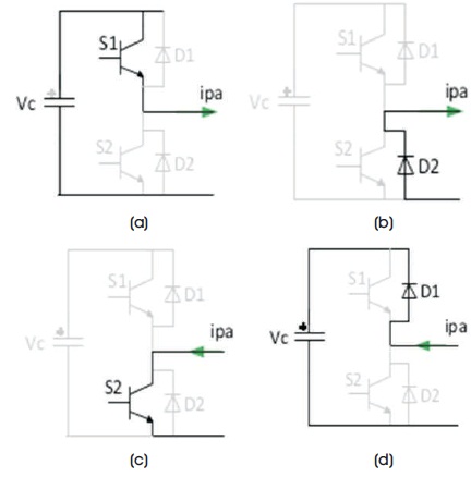
Figure 2. Stages of Operation for a Half-bridge Module (a) Inserted Sub-module, Capacitor in Discharge Mode; (b) & (c) Sub-module Bypassed, (d) Sub-module Inserted, Capacitor in Charging Mode (Purkait & Pandey, 2018)
Other sub-modules present in MMC topology are (Solas et al. 2013) as follows,
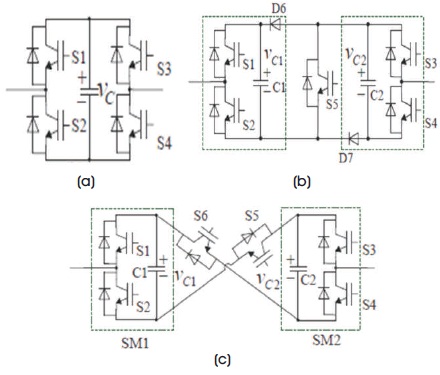
Figure 3. Schematic of the Sub-modules used in MMC (a) Full Bridge, (b) Clamp Double, (c) Five-level Cross Connected (Purkait & Pandey, 2018)
Table 1 shows a comparison of different parameters like fault handling, losses, and voltage levels in different sub-modules. Half-bridge usage is more popular as the number of devices is two and losses are less compared to other sub-modules.
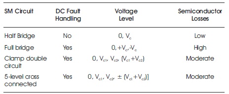
Table 1. Comparison of Sub-modules
MMC topologies are basically three as shown in Figure 4 (Nabae et al.,1981; Khoshkbar - Sadigh et al., 2016).
(a) Cascaded H-Bridge Converter (CHB),
(b) Neutral-Point Converter (NPC), and
(c) Flying Capacitor converter (FC)
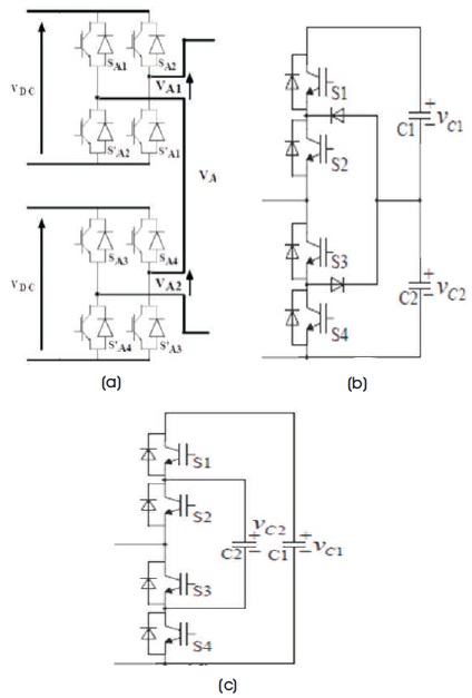
Figure 4. MMC Topology (a) CHB, (b) NPC, (c) FC
Modulation based on triangular carrier waves is usually preferred with phase shifting and level shifting (Hagiwara & Akagi, 2009; Konstantinou et al., 2013). Both of these perform modulation at high switching frequencies. In phase shifted carrier wave modulation, all the modules are equally used and lower harmonics are produced. On the other hand, in level shifted carrier wave, modulation carrier waves are stacked one over the other. Each one of the carrier is assigned its own sub-module. The module has to be either applied or bypassed when compared to a reference signal. The limitation of carrier wave modulation is that the switching losses are higher when compared to fundamental frequency modulation.
Selective Harmonics Elimination (SHE) is also used, but the problem of complexity in finding switching angles at increased number of levels limits the usage (Guan et al., 2011). Another option Nearest Level Modulation (NLM) is also preferable as it is more simple and performance wise it is good. NLM sometimes fit to MMC because of low harmonics and low amplitudes of voltage.
For steady-state-stable operation, the control on average capacitor voltage must be done, stress on sub-module cells must be equalized, influence of circulating currents should be taken into account (Perez et al., 2015). The controls to be taken care of are as follows:
1. Arm Current - Arm voltages are responsible for configuration of the converter for which each arm current is to be controlled on both input and output side.
2. Circulating Current - It is often seen that certain amount of circulating current flow through the arms of MMC caused due to instantaneous change in voltage levels. This issue is solved at the time of multilevel modulation.
3. Capacitor Voltage Balance - Capacitor voltages are also required to be controlled at a reference level and at the same time balanced inside and among each arm. The capacitors that exceed the voltage limits is multiplied by a factor of correction to further increase their likelihood to be inserted or bypass in the subsequent switching cycle.
For a converter to be reliable, it is necessary to study the size of the inductor and capacitor, the sub-module numbers, arm current, current and voltage ripples, semiconductor losses, and short circuit current. Several alternate topologies for MMC converter have come into the picture, such as hybrid MMC (Yang et al., 2012), matrix MMC (Kammerer et al., 2012), hexagonal MMC (Baruschka & Mertens, 2013; Li et al., 2013), etc. Although they improve MMC characteristics to some extent in return lose modularity and reliability of the converter designed.
1. Design and Implementation - MMC should be made compact by controlling the size of capacitors and limiting flow of circulating currents, minimizing ripples (Yang et al., 2011). A trade-off between voltage ripple, size, and cost decides the sub-module size. Guan et al. (2010) have carried out an analysis under wide range of operating conditions for the sub-module capacitor voltage ripple.
2. Calculation of losses - Both switching as well as conduction losses are present in the converter. Through data-sheets of semiconductor devices from the manufacturer and the SM current flows, conduction losses are determined. Switching losses have dependency on transitions like insertion/ bypass. Using analytical analysis (Rohner et al., 2010) or simulation (Modeer et al., 2011; Li et al., 2013; Miet et al., 2009) one can calculate the overall semiconductor losses.
3. Fault Mitigation - Presence of a large number of redundancies enables fault tolerance in MMC. To identify which sub-module experiences fault when identical sub-modules are present, sensors are installed with each sub-module. This increases cost and system complexity. Also by placing control system to locate the device failures, modification is provided to the converter structure. Study of the high current dynamics of modular multilevel converter shows a short circuit current limitation tactic that the converter itself exhibits to handle DC faults (Marquardt, 2011).
4. Capacitor Pre-charge - The capacitors are charged to a nominal value at normal state. High converter capacitance often leads to development of high inrush currents during the process of charging at start-up of the converter or after a fault. To escape this, series resistor connection is made temporarily to the converter (Das et al., 2011). This lacks energy efficiency leading to big and bulky resistances in service at the high voltages.
Another tactic is staggered sequence capacitor charging by providing delay in the charging of each capacitors (Xu et al., 2011). There is more complexity in control system.
5. Voltage Ripple - By limiting arm currents and power losses in converter, it is possible to reduce voltage ripples. In addition to reduction of voltage ripples, maximization of the operating region using second harmonic circulating current is done through shaping of the capacitor voltage ripple (Vasiladiotis et al., 2012) or by use of circulating current consisting second harmonic and a common-mode third harmonic phase voltage (Ilves et al., 2011), etc.
MMC has applications into a very wide range like HVDC transmission (Gemmell et al., 2008), active power filtration, FACTs controllers, power quality improvising, medium/high voltage drives, and electric traction systems, etc. Some of these are listed below:
Other area of applications includes active filters and medium voltage drives. MMC-based STATCOM used as FACTS controller is discussed in (Guying et al., 2012), which consists half-bridge SMs for active filtering of unified powerflow controller based on the concepts of MMC.
MMC has emerged as a most successful DC-DC converter. Researches are conducted to further revolutionize its use by reducing the size per unit volume even more, reducing semiconductor losses, and cooling system needs. Its modular nature is exploited to inbuilt fault tolerance to manage DC faults without having bulky and costly circuit breakers. Considering productive benefits of MMC operations, it can be used in medium voltage, low voltage, and in photovoltaic plants to increase the storage of energy in the plant so as to utilize it during night. Machines can be connected directly to medium voltage grids as MMC has the high voltage capability. In view of power quality, low voltage applications can also be benefited from MMC. There is a large scope for future development in the case of medium voltage variable speed drives and to address the issues of operation and control during constant-torque-low speed operation.
A novel boulevard on research and development in MMC has given us a wide scope for application purposes. Its salient features like modularity and scalability allows us to meet up any requirements of voltage; its high efficiency has a significant role in HVDC applications; identical sub-modules provide superior harmonic performance and reduce filter size drastically. The use of half bridge is considerable due to its ease in application, also its voltage values are easily scalable and redundancy is easy. To design a converter either with boost, buck, or buck-boost capability a half-bridge configuration is preferred over others. The issues is balancing of the capacitor voltages, which can be removed to a greater extent with the help of suitable modulation techniques. The paper has brought all the conceptual facts regarding its modeling, operation, issues to control, and techniques for modulation. It is hence very clear that in future newer demands will be generated for which new devices will be invented which will drive and shape the Modular Multilevel Converter technology.