(1)
In this generation of Internet of Things (IoT), a lot of image processing algorithms are applied on high resolution displays which are used in mobile devices of various sizes. It becomes vital to design a high speed and low-power image processing algorithm for high speed transmission and processing of data. This paper proposes a progressive design of 2D-DCT and quantization which is one of the abundantly used image processing algorithm and is realized using Dadda and Vedic multipliers which work in real time exceptionally in both parallel and pipelined process for calculating 2D-DCT. The high speed, accuracy and less hardware complexity of the proposed systems outclass with those of other presentday systems. The frequency of proposed system is increased to 185.048 which is 19% when compared to the prevailing systems. The proposed system architecture can be easily modified to compute 2D-IDCT which decompress the coefficients to get the image value.
Cutting edge communication systems fiat uses fast algorithms for realization of video processing applications. The rudimentary processing of video requires partitioning the video into sub image frames and then compressing every sub frame. Discrete Cosine Transform (DCT) [1] , Wlash Transform, Set Partition in Hierarchical Trees and Discrete Wavelet Transform (DWT) are the image transforms that are applied for the compression of images.
JPEG is the one of the most widely used image compression standards and it is the transform used in the jpeg standard. Even with the emergence of the more subtle transforms such as DWT, the DCT has not been completely excel primarily due to its simpleness. The DWT performs better in terms of compression ratio, but the DCT trumps over DWT, for its computational speed and simplicity. If DWT is preferred over DCT, it trails in Peak Signal to Noise Ratio (PSNR) for raster images is not greater than 1dB [2], [3].
The 2D-DCT is a good substitute which involve real time image processing. Due to its simple nature it is used in many image, audio and video compression standards including ITU H.261 for teleconferencing, JPEG2000 for raster image compression, and ISO MPEG1/ MPEG2 for video compression [4] and mp3 for audio compression.
DCT is one of the computationally intensive algorithms, so there is an ardent need of parallel and pipelined process for high speed computation. An abundant research is conducted on DCT algorithm to calculate the architectures which gives optimal performance for a given area, low power consumption and high throughput. DCT can be realized in many ways and the most notable methods are row-column decomposition which is used in the proposed system and Distributed Arithmetic (DA) [5] , [6]. In this paper, the proposed system uses matrix multiplication to get the 2D-DCT coefficients and then succeeded by quantization stage.
In [7] DCT is optimized by using frequency analysis for the synchronous design to compute the DCT coefficients. The design is carried on Xilinx VertexIV FPGA device. The architecture used in the system is distributed arithmetic. By using DA, maximum operating frequency of 118.2 MHz is obtained.
Using constant multipliers based on Canonical Signed Digit (CSD) 1D-DCT algorithm is calculated in [8] which decreases the number of registers, adders and subtractors. The total design is implemented on the Spartan3E FPGA device and the design runs at 110 MHz of clock frequency.
In [9] 2D-DCT is implemented using a time- multiplexed rowparallel architecture. The design uses Arai algorithm with Algebraic Integer encoding. The total frequency of the system runs at 121 MHZ.
A one dimensional radix-8 DCT is calculated using integer encoding technique in [10]. The system efficiency is increased by using efficient algebraic integer encoding techniques.
A direct row-column multiplication is used for calculating the 2D-DCT is proposed in [11], which use high speed 8x8 and 11x8 Vedic multipliers for calculating the 2D-DCT coefficients. The proposed system is based on [11, 12]. The proposed design further increases the frequency of the system.
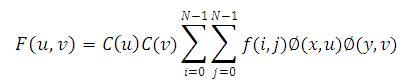
The 8-point 2D-DCT of real data sequence is defined by,
Where,
F(u,v) is the 2D-DCT basis functions.
f(i,j) = Image values
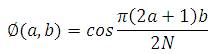
for u,v = 0,1,2,….N-1
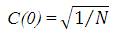
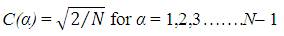
and the DCT sampling rate is given by 'N'.
This paper presents the 8 point 2D-DCT so N=8.
For N=8 equation (1) represents 3 orthogonal 8x8 matrices which can also be written as,
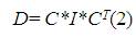
Here C is the cosine values and I is the Image values and CT represents the transpose of the Cosine matrix C.
This algorithm can be implemented in two basic stages.
In stage 1, the product of C*I is calculated.

In the stage 2 the product of P*CT is calculated to get 2DDCT basis functions.

The proposed design consists of the Row*Column multiplication, 8x8 of different bus widths to get 2D-DCT coefficients. A highly parallel and pipelined architecture is used to get 2D-DCT and quantization values.
Initially, the image is taken and is segregated into blocks. Each block is of 8x8 pixels data. Every pixel consisting of 8 bits of data. Pixel value ranges from 0 to 255.
In stage 1, 8 pixels of data is given to the 8 Dadda multipliers where other input is from the ROM module as shown in Figure 1. The output is then added in 12 bit CSA to get P.
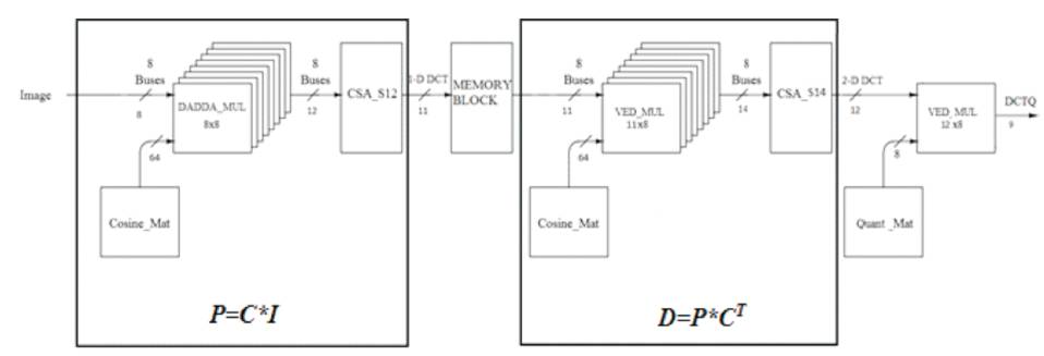
Figure 1. Architecture of 2D-DCT and Quantization
Similarly, Stage 2 consists of 11x8 Vedic multipliers for which their output is added in CSA 14 to get 2D-DCT values.
In the final stage, the output are quantized using 12x8 Vedic multiplier.
Numerous multiplier algorithms are studied in [13] . Wallace tree multiplier, Computation Sharing Multiplier (CSM), Dadda multiplier and Vedic Multiplier has been conducted. From the studies it can be concluded that Dadda algorithm and Vedic gives high speed of operation compared to any of their other counterparts. Least area is consumed by Vedic and Dadda multipliers. Thus Dadda multiplier is used for the implementation of 8x8 bit multiplication as it performs faster than Vedic without any significant increase in the area. The design incorporates 8 multiplier units which are parallel. Each Dadda multiplier has two inputs one from ROM and other from Image.
The unsigned Dadda multiplier is shown in Figure 2. It shows the unsigned multiplication. The above multiplier is again converted into signed multiplier for the 1D-DCT computation.
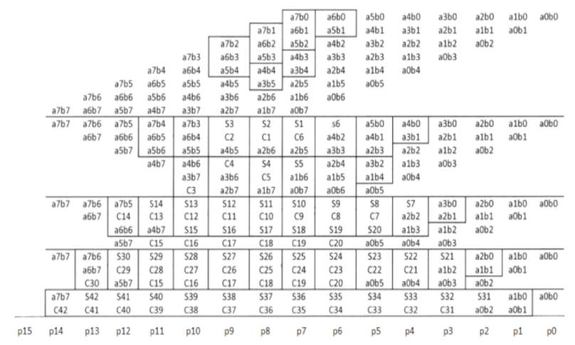
Figure 2. Illustration of 8x8 Dadda Multiplication
One input to the multiplier is the 8 bit image values which ranges from 0 to 255 and other input is the 8 bit signed numbers ranging from -128 to 127. Higher frequency is achieved due to the parallel and pipelined architecture of the multipliers units.
Signed Vedic multipliers are also used for calculating the DCT coefficients of different bus widths. The architecture is shown in Figure 3.
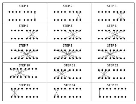
Figure 3. Illustration of 8x8 Vedic Multiplication
Vedic is preferred in the second stage of Dadda because of its ability to multiply the uneven bit widths.
ROM (Read Only Memory) is the Program memory used in the system. Modified cosine terms is stored in the ROM module. The elements of the 8x8 cosine terms are stored as 8 row elements which are concatenated to get 64 bits length and single column elements taken in the 1's complement form. This type of storing gives easy access to the memory and helps to save the memory. A complex job in designing the ROM is to interpret the cosine values. Usually cosine values consists of floating point numbers that are used in the DCT and are shown in Figure 4.
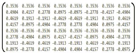
Figure 4. Cosine Values
The floating point multiplication is highly complex when compared to integer multiplication and also it takes large area.
This paper proposed a new method to do integer multiplication without bothering about floating point multiplication. The integer cosine values are shown in Figure 5.
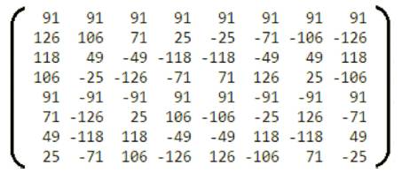
Figure 5. Modified Cosine Values
Every cosine values in Figure 4 are multiplied with 256 to get the integer values in Figure 5.
The proposed model uses 1's complement instead of 2's complement to store in ROM modules. Due to this, the computational complexity is highly decreased and the operating frequency is increased.
The addition in digital domain can be carried out by diverse adders such as Carry Select adder, Carry Skip adder, Carry Save adder, Carry Look Ahead adder and Ripple Carry adder. Least amount of area is consumed by Ripple Carry adder and Carry Save adders, but a high frequency of operation is provided by Carry Save and Carry Skip Adder. Considering the high frequency and least consumption, carry save adder is considered for the proposed design.
The system uses 12 bit and 14 bit signed carry save to get 1D-DCT and 2D-DCT values. The pipelined stages for 12 bit and 14 bit irrespective of bit lengths, the only difference is their delay.
The adder is designed such that it takes less number of stages to do the computations in pipelined manner to calculate the addition of 8 buses.
The carry save adder which is used in the system is shown in Figure 6.
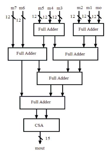
Figure 6. Carry Save Adder
Memory block is represented in Figure 2. It takes 11 bit values from CSA and stores for 7 clock cycles. At eight clock cycle it gives out the parallel data to 8 Vedic multipliers.
The proposed design is modeled in Xilinx ISE Design Suite 14.5 and implemented on SPARTAN-3E FPGA device. The FPGA device exhibited the following utilization: 3518/9,312 as slice registers. The utilization summary of the device is shown in Table 1. The proposed design gives maximum path delay of 5.404 ns, which yields a maximum operating frequency of 185.048 MHZ.
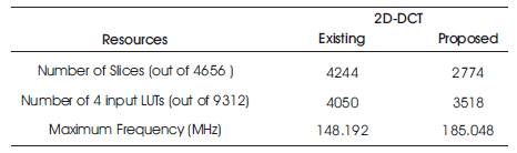
Table 1. Device Utilization Summary
Figure 7 shows the simulation results of 2-D DCT. The signal “clk” is the clock input to the 2-D DCT. Input signals are i0, i1, i2, i3, i4, i5, i6 ,i7. The input signals are given to the 8x8 Dadda multipliers and then their 16 bit output is truncated to 12 bits. The output of the multipliers are given to CSA to get 15 bits of data and then later truncated to 11 bits, i.e “sumout”, which is the value of 1D-DCT. The 1D-DCT values are later stored in a stack for 7 clock cycles and is given to the 8, 11x8 Vedic multipliers which gives 19 bit output and then truncated to 14 bit output, and is given to CSA to get 12 bit output. The final output obtained is the 2D-DCT values and later given to the quantization.
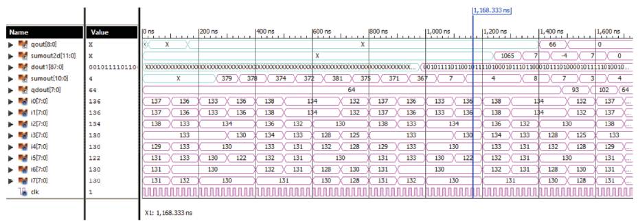
Figure 7. Simulation Results of 2D-DCT
This paper presents a highly area efficient and high-speed 2D-DCT which is computed using Dadda and Vedic multiplier units which are highly parallel and pipelined architectures. A new method of integer multiplication is introduced instead of floating point multiplication which greatly reduces the complexity of the system and increases the frequency of the system. The quantization is carried after the calculation of the basis values.
The system can be further extended to 2D-IDCT to get the compressed values. Performance of the system can be further improved by using more efficient multiplication algorithms and cosine values.