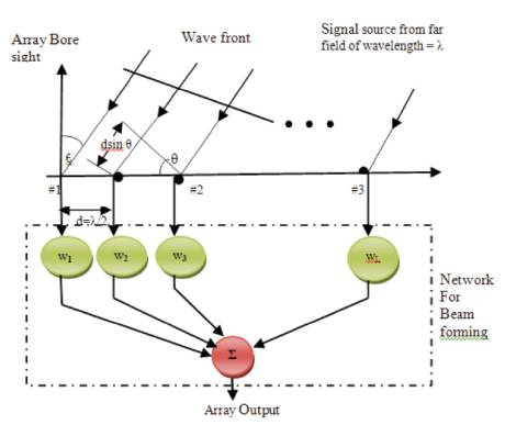
Figure 1. Signal Model of Smart Antenna System
In this paper, the authors analyzed the performances of well known array signal processing algorithms for adaptive beam forming namely, Sample Matrix Inversion (SMI), and Least Mean Square (LMS) algorithms. From the simulation results, it is observed that, for SMI as the number of user increases, the main lobe spreads in all the directions. As a result of this, beam forming in the user direction may not be accurate. To overcome this problem, LMS algorithm can be used. The LMS algorithm is a best choice in most of the commercial wireless applications due to its low complexity. 5G and beyond 5G networks require beam forming algorithms with high directivity and fast converengence rate. Hence, in this work, they have modified the LMS algorithm to improve the converengence rate and then they applied improved LMS algorithms to horizontal-vertical Uniform Linear Array (ULA). This is also called as two dimensional ULA (2D-ULA). Hence these algorithms are called as 2D-LMS1 and 2D-LMS2. Simulation results show that the proposed algorithms have improved convergence rate, directivity as compared to conventional LMS algorithm. Hence these algorithms are best suited for 5G and beyond mobile communications.
Smart antenna system involves, processing of incoming signals induced on various antenna elements. It has a great potential to steer the nulls to reduce the co-channel interferences [1]. Smart antenna system enhances the system capability by directing the narrow beams towards the user of interest, while nulling other users not of interest. Smart antenna systems are getting huge popularity because of their capacity to suppress the side lobes, improved System capability, Space Division Multiple Access (SDMA), High bandwidth, Multipath suppression, increased frequency reuse and improved array resolution [2]. Because of these potential benefits, smart antenna system finds wide range of applications. Some of the applications not limited to are, mobile communications, Satellite communications [3], Multiple Input Multiple Output (MIMO) systems [4], Wireless Local Area Networks (WLAN) [5], Radar [6], Ubiquitous Radar [7] , Mobile Adhoc Networks (MANET) [8], Wireless Local Loops (WLL) [9], Waveform diversity systems [10] etc. Smart antenna is a major element to fulfill the high data rates of modern smartphones [11]-[14], and will be a key component for Millimeter-Wave beam which is forming as an enabling technology for 5G cellular communications [15]-[18] . A signal model of antenna array system is shown in Figure 1. The antenna array is one of the constitutive parts of a smart antenna. It consists of 'L' identical independent antenna receivers separated in space allocated in a geometric form. By increasing the electrical size of the array, highly directive radiation patterns are formed. Moreover, the multiplicity of elements allows more precise control of the radiation pattern resulting in lower side lobes or fine pattern shaping .
Figure 1. Signal Model of Smart Antenna System
Let us consider a system model with ULA consisting of 'L' isotropic sensors and 'd' as inter element spacing of ULA and its value is chosen to be λ/2 in order to reduce mutual coupling effects. The narrowband signal received by a linear antenna array with L - Omni-directional antenna elements, at the time instant n can be expressed as:
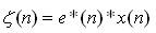
Where, s(n), i(n) and no(n) denote the L×1 vectors of Signal Of Interest (SOI), Interference and Noise respectively. For simplicity, all these components of the received signal of equation (1) are assumed to be statistically independent to each other. This assumption is fairly practical since the SOI and the signals from interferers (other objects or users) are typically independent. The conventional (forward-only) estimate of the covariance matrix defined as,
where σ2 is the noise power at a single antenna element, I denotes the identity matrix and (•) H and E [•] stands for the Hermitian transpose and Mathematical expectation respectively.
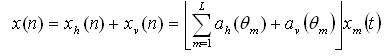
It consists of doubly crossed ULAs, i.e., superposition of horizontal and vertical ULA, has identical size and computational load as compared to ULA. Figure 2 shows the geometry of horizontal–vertical ULA. Now, let us apply all the components of the received signal of equation (1) to the above geometry to analyze the performance. Hence, the user signal x(n) can then be modeled for k snapshots as:
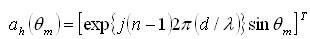
Where, ah(θm) and av (θm) are the L x 1 array steering vectors of horizontal- and vertical array respectively. The expressions of these steering vectors are given by:
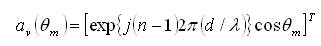
The array manifold vector corresponding to 'm' source directions θ1, θ2,.....,θm for horizontal and vertical arrays can be expressed as,
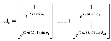
Where, Ah and Av are the horizontal and vertical array manifold vectors respectively.
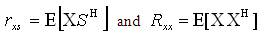
Now, let us obtain signal samples 'S' by sampling continuous time signal of baseband frequency (for simulation cosine wave samples are considered). Then Lx1 cross-correlation matrix rxs and LxL covariance matrix Rxx is computed using
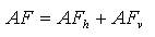
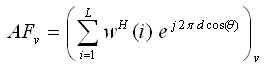
The Array Factor (AF) expression for the proposed algorithms using 2D-novel antenna array can be obtained as,
Here:

The value of θ in equation varies between -90o ≤ θ + 0.001 ≤ + 90o and WH (i) is hermitian transpose weight update vector.
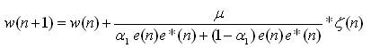
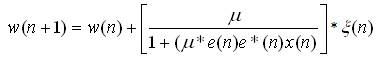
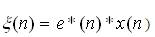
In this method, the authors have modified the weight equation of classical LMS algorithm as,
Here,
W (n+1) = updated array weights,
W (n) = previous weights


In the above equation, the value of x(n) can be expressed for 2D-ULA as,
The authors further simplified the weight updating equation of 2D-LMS 1 as,
Here,
W (n+1) = updated array weights,
W (n) = previous weights.
The proposed algorithms are simulated using MATLAB software. The parameters used in the simulations are tabulated in Table 1. Angle for beam forming, which is the o mobile user direction is considered at 0 . The noise is modeled as a stationary zero-mean spatially and white complex Gaussian process. The beam scanning of the proposed 2D-LMS 1 and 2D-LMS 2 algorithms are implemented and the results are illustrated in Figures 3 and 4. The radiation pattern of SMI, 2D-LMS 1 and 2D-LMS 2 are compared in Figures 5 and 6 for antenna array elements 10 and 15 respectively.
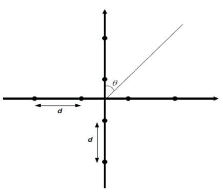
Figure 2. Geometry of Horizontal–Vertical ULA (2D-ULA)
Table 1. Experimental Parameters
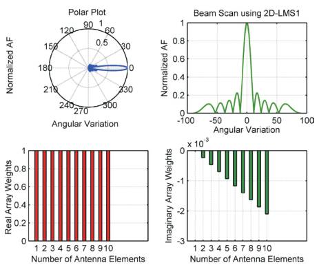
Figure 3. Beam Steering Process Using 2D-LMS 1
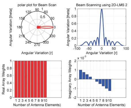
Figure 4. Beam Steering Process Using 2D-LMS 2
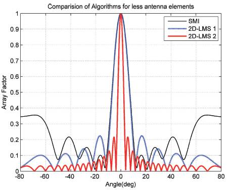
Figure 5. Radiation Pattern of 2D-LMS 1 for L=10
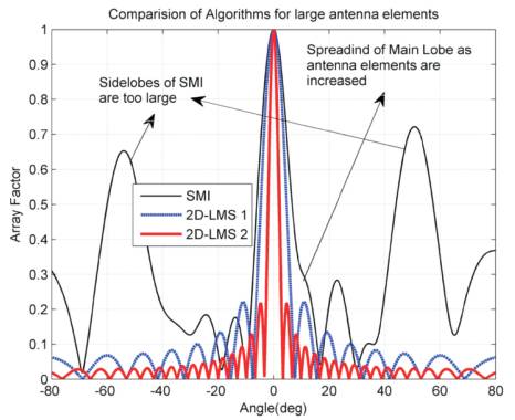
Figure 6. Radiation Pattern of 2D-LMS 2 for L=15
In Figure 5, the authors note that, all three algorithms form beam with main lobe towards the look direction when the antenna elements are less (L ≤ 10). As antenna elements are increased, the SMI algorithm deviates from its performance and spreads the main beam which is shown in Figure 6. It is also worth to note that, the proposed algorithms produce the main lobe towards the user direction for both small and large array antenna cases. Furthermore, the main lobe of both the algorithms is narrow, indicating high directivity as compared to normal LMS algorithm [2]. Here as compared to 2D-LMS1, the directivity of 2D-LMS 2 algorithm is high.
Figure 7 shows the MSE comparison of beam formers. Normal LMS algorithm takes more than 90 iterations to converge to zero this corresponds to more than half of the period of the waveform of interest. The proposed algorithms converge within 50 and 40 iterations for 2D LMS1 and 2D LMS2 respectively. Hence the proposed algorithms can track the desired signal faster and in a satisfactory manner even when signal characteristics are changing rapidly as compared to normal LMS, normalized LMS (NLMS) [16], and Variable Step Size NLMS (VSSNLMS) [17]. Directivity of the antenna system is directly related to the sharpness of main beams. Use of horizontal-vertical ULA makes the main beam sharper. This increases the directivity of the antenna system. Hence the proposed methods have sharp main beam and thus have high directivity as compared to normal LMS algorithm.
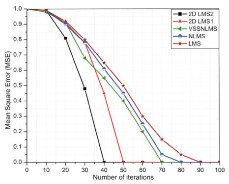
Figure 7. Convergence Analysis Beam Forming Algorithm
In this paper, the authors have implemented two adaptive beam forming algorithms based on well known LMS algorithm using 2D-ULA configuration. The LMS algorithm is improved in terms of computational complexity, convergence rate, and directivity. From Figures 5, 6 and 7, it is clear that, the proposed algorithms have low complexity, high convergence rate, and high directivity as compared to conventional algorithms. Hence the proposed LMS algorithms outperform existing methods and can be used for next generation high speed cellular communications.