(1)
This paper presents a new window for designing FIR low pass filter. While designing a FIR filter, there are two important parameters which must be taken care of which are transition width and ripples. Transition width should be as small as possible and ripples should be less both in pass band as well as stop band. There are different windows like Rectangular, Triangular, Hanning, Hamming, Blackman, etc., which are used for filter designing. The proposed window which is a modified form of Blackman window contains four cosine parameters and the simulation result shows that this window has better response when compared to Blackman Window.
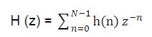
A Filter is used to reject unwanted frequencies from the input signal and allow the desired frequencies. A digital filter is a linear time-invariant discrete time system. It is used to remove unwanted noise to provide spectral shaping or to perform signal detection or analysis [10]. Digital filters are capable of per forming that specifications which are extremely difficult to achieve with an analog implementation because various characteristics of a digital filter can be easily changed under software control. Two types of filters which provides these functions are Finite Impulse Response (FIR) Filters and Infinite Impulse Response (IIR) filters. The FIR filters are of non-recursive type, whereby the present output sample depends on the present input sample and previous input samples, whereas the IIR filters are of recursive type, whereby the present output sample depends on the present input, past input samples and output samples. The range of frequencies that are passed through the filter is called passband and those frequencies that are blocked is called stop band [3]. In practice, FIR filters are employed in filtering where there is a requirement for a linear-phase characteristics within the passband of the filter. If there is no requirement for a linear phase characteristics, either an IIR or FIR filter may be employed [2]. The issue of which type of filter to design, FIR or IIR, also depends on the nature of the problem and on the specification of the desired frequency responses [8] . The z-tranform of a N-point FIR filter is given by [5] ,
There are essentially three well known methods for FIR filter design namely,
A simple and efficient way to design an FIR filter is window method. In the Window Design Method, the unit impulse response of ideal filter is obtained by applying inverse Fourier transform to the ideal frequency characteristics of the digital filter. Then this unit sample response must be truncated at some point, this process is equivalent to multiplying it by a finite length window function. After truncation and windowing, FFT is used to generate the corresponding frequency response of the FIR filter [6] . The frequency response can also be modified by choosing different window functions. The ideal desired frequency response can be represented as,
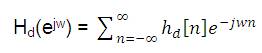
where hd[n] is the corresponding impulse response sequence which can be expressed in terms of Hd(ejw ) as [1],
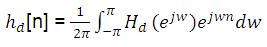
In general, unit sample response, hd[n] obtained from the above relation is infinite in duration but it must be finite. One effective way is to cut off hd[n] which means using a finite length window sequence to intercept hd[n] for turning non-causal sequence into causal [4].
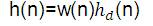
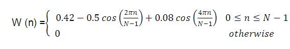
where w(n) is the window function.
While designing a digital FIR filter using window function, it is necessary to specify a window function to be used and the filter order according to the required specifications (selectivity and stop band attenuation). These two requirements are interrelated. Each function is a kind of compromise between the two following requirements, i.e. the higher the selectivity, the narrower the transition region and higher the suppression of undesirable spectrum, higher the stop band attenuation. There are different windows which can be used for designing FIR filters. The main aim of a window function is to provide accurate type of responses with reduced side lobes and comparatively less pass-band and stop-band ripples [11].
Methodology is the systematic way to achieve the objectives. Various window techniques are studied from research papers to design FIR filters. MATLAB software is used to compare the results of various window functions. The Modified Blackman Window function is also implemented in MATLAB software, the results of which are discussed in the simulation section.
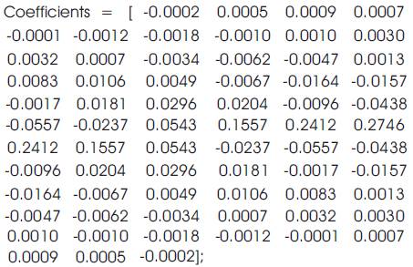
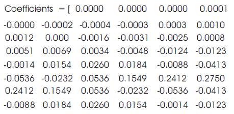
During filter designing, the main requirements are that the transition width should be less and the side lobes should be minimum. Transition width depends on filter order. Higher the filter order, lesser is the transition width. Ripples depend on the smoothness of the window. Filter order doesn't play much role in deciding ripples. Smoother the window, lesser will be the ripples. Among Hanning, Hamming and Blackman window, Blackman window has better response as compared to other windows. Side lobes are minimum in Blackman window. Blackman window has more terms compared to Hamming window and Hanning window. More terms in calculation indicate more accuracy in the result. For this reason, the result and the simulation are more accurate in this window. The extra cosine term in Blackman window reduces the side lobes. This is the concept which is used in the new proposed window. The new proposed window contains four cosine terms.
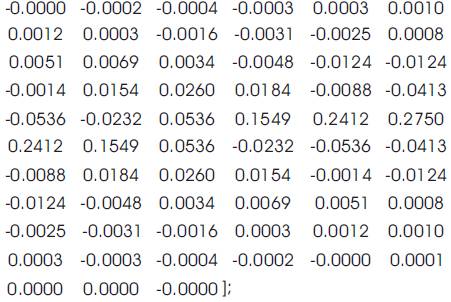
Window function of the new proposed window is
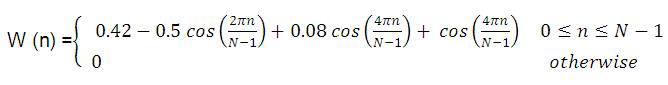
where p = .004
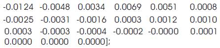
Now authors compare the response of different windows with the Newly Proposed Window or Modified Blackman Window. The concept which is discussed above, i.e. more the cosine terms in the window function, better will be the results, is used in the New Proposed Window.
By using MATLAB, design the FIR Low Pass filter to meet the specifications given below by using window method. Although any filter specifications can be taken but for the sake of implementation, the following specifications are considered for the low-pass filter:
Pass band edge frequency – 1000 Hz
Stop band edge frequency – 1200 Hz
Pass band attenuation – 0.2 dB
Stop band attenuation – > 65 dB
Sampling frequency – 8000 Hz
Transition width = 115 Hz;
First Peak Side lobe = -44 dB.
Transition width = 121 Hz;
First Peak Side lobe = -53.4 dB.
Transition width = 172.75 Hz;
First Peak Side lobe = -75 dB.


Transition width = 171 Hz;
First Peak Side lobe = -86.4 dB.
The implementation cost of the new proposed window is shown in Figure 5.
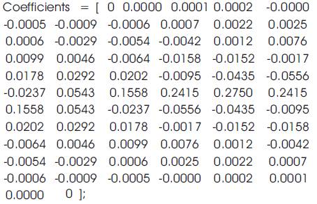
After simulation it is found that, the filter order obtained is 66 in all the above windows. Filter order should be as low as possible to have less complexity.
After comparing the response of above windows, it is clear that the New Proposed Window has a better response compared to all other windows in terms of both transition width as well as stop-band attenuation (Table 1).
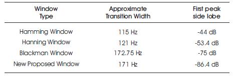
Table 1. Comparison Table for all the Windows
From simulation, if we compare the response of Hamming, Hanning and Blackman windows (i.e. Figure 1, Figure 2 & Figure 3), it is clear that Blackman window has more stopband attenuation as it has less side lobes in the stopband. The transition width of Blackman window is large as compared to the rest of the two windows. This indicates that the transition width and stopband attenuation are two interrelated terms. If we want to increase the stopband attenuation, then transition width also increases. So, we must choose the window carefully which satisfies both the requirements. Blackman window has more terms as compared to Hamming and Hanning windows. More terms in calculation indicate more accuracy in the result. The new proposed window (Figure 4) has more terms as compared to the Blackman window, i.e. it has four cosine parameters and the results obtained are better than even Blackman windows. Its stopband attenuation is -86.4 dB, which is approximately -11 dB more than the Blackman window. The transition width of this window is also 1.75 Hz less than Blackman window. So, the new proposed window provides better response than Blackman window in terms of both transition width and stopband attenuation.
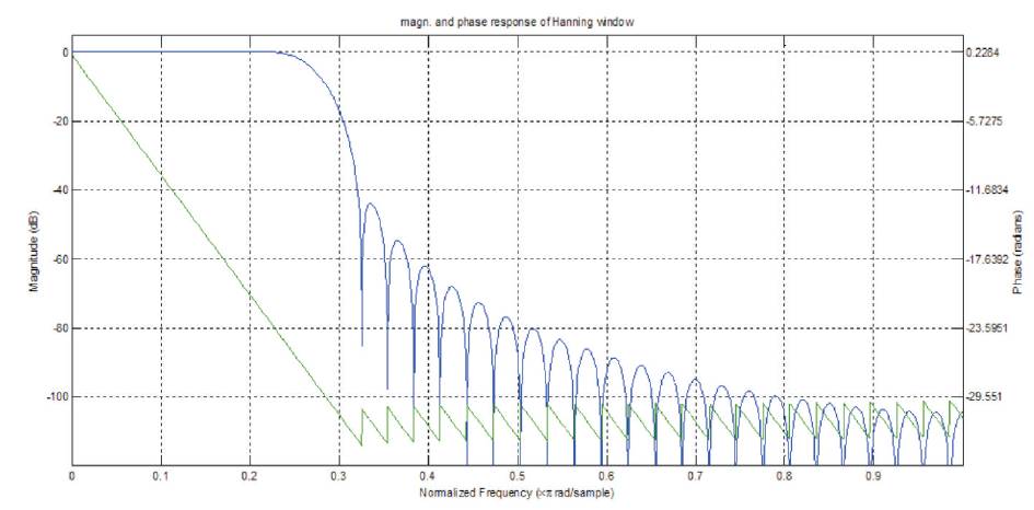
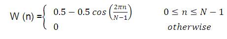
Figure 1. Hanning Window Response
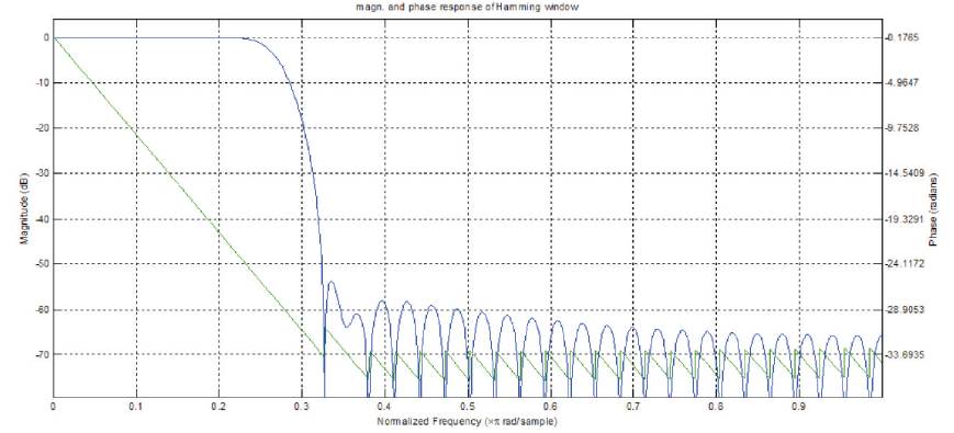
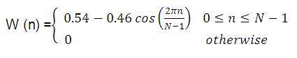
Figure 2. Hamming Window Response
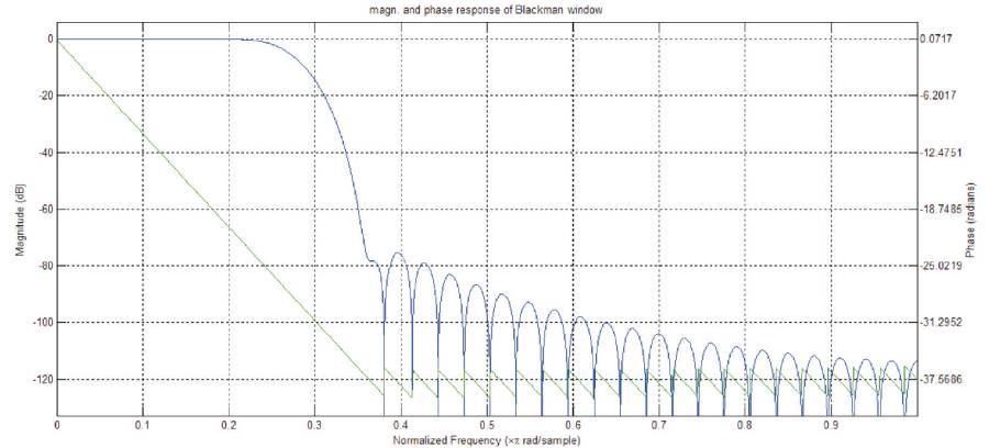
Figure 3. Blackman Window Response
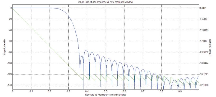
Figure 4. New Proposed Window Response
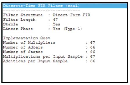
Figure 5. Implementation Cost of the New Proposed Window
In future, the present work may be extended on the following lines: