Figure 1. NN Coherent SDM Transmission based on MIMO DSP
The objective of this review paper is to make readers understand the key terms related to optical fiber specifically few mode fiber to help them carry out further research work. With the increasing demand for faster transmission systems, optical fiber communication system requirement is increasing day-by-day. As we know that the capacity limits of single mode fiber is almost reached its maxima, Space division multiplexing can be helpful for increasing the data rate requirement. This review paper, inferred the transmission of 6 spatial and polarisation modes, each carrying the quadrature-phase-shift-keyed channels over few-mode fiber keeping lower differential group delay. The detection of these channels is being carried out using coherent detection namely MIMO DSP. The 66 impulse response matrix representation of few-mode fiber is presented, revealing the coupling characteristics between the modes.
Single-Mode Fibers (SMFs) have been successfully exploited for long-distance optical transmission for over decades, at the same time their capacity continuously grew by three orders of magnitudes. The growth was improved by the successive introduction of Wavelength- Division Multiplexing (WDM) technique, Polarization-Division Multiplexing (PDM) technique, and higher-order modulation formats [1] known. Eventhough the capacity of SMFs is now approaching the limits imposed and calculated by the combination of Shannons information theory and nonlinear fiber effects [2]. In order to continue to grow the capacity and fulfill demands, a new dimension is now demanded and it has been suggested [3] that Space Division multiplexing (SDM) be utilised as a technique for enhancement in capacity of the optical transmission systems. In SDM, spatially distinct paths are used to transmit multiple channels, and if realized over a single fiber, SDM offers a significant potential for cost-, space- and energy savings [4]. SDM over a single fiber can be achieved in 2 different ways. The very first technique consists of using waveguides that support multiple distinct waveguide modes, such as in a Multimode Optical Fiber (MMF). Earlier attempts of SDM over MMF [5]-[8] were limited in lower transmission distance and bandwidth, because the waveguide modes supported could not be selectively excited and detected and also because of the increased modal Differential Group Delay (DGD) present in the standard multimode fiber. Most recently transmission distance and bandwidth has been increased and enhanced by using Few Mode Fibers (FMFs) [9]-[14] which are MMF that support only a small and fixed number of waveguide modes. In this work, the FMF transmission distance is further extended up to 137 km at 240 Gbit/s single wavelength channel bandwidth [15]. For such a transmission distance, significant crosstalk between all modes offered by the FMF can be observed, and MIMO DSP for crosstalk reduction is required.
The second technique to implement SDM consists of multiple spatially distinct parallel waveguides formed and are consisted inside the fiber. The simplest implementation is given by the Multi-Core Fiber (MCF), and consists of multiple cores distributed and placed across the fiber section. In this technique, it is desirable to reduce the crosstalk between cores so that the individual cores can be considered as individual channels, thus greatly simplifying the communication system design and modelling. Eventhough the cores are spatially separated, achieving low crosstalk between cores for long haul transmission, can be a challenging task because the light is not completely confined and constricted in the cores of fiber.
However recently low crosstalk 7-core MCFs have been demonstrated [16]-[17] using core spacings of >45 m and non-standard cladding diameters >150 m. In this work we show that the fiber design can be drastically simplified, and the spacing between the cores are reduced to < 30 m, if crosstalk is allowed and subsequently undone by Multiple- Input Multiple Output (MIMO) Digital Signal Processing (DSP). Despite having large crosstalk, transmission distance have been improved apparently.
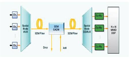
The general method to perform SDM transmission over FMF or CCF in the presence of crosstalk or coupling between the SDM channel is shown in Figure 1.
Figure 1. NN Coherent SDM Transmission based on MIMO DSP
The signals from N transmitters are coupled into the SDM fiber by an SDM Multiplexer (SDM-MUX). After transmission through the SDM fiber, the received signals are demultiplexed by a SDM Demultiplexer (SDM-DEMUX) and fed into N coherent receivers. The received signals are subsequently processed using MIMO DSP.
In order to achieve the full SDM capacity gain of a factor N at high reliability (i.e. low outage), it is required that the NN transmission channel consisting of SDM-MUX, SDM fiber, and SDM-DEMUX to be described by a unitary linear transfer function [18]. In particular this requires that the SDM-MUX and DEMUX is capable of exciting all the modes supported by the SDM-fiber in a selective way. For the SDM fiber, the requirement implies negligible Polarization Dependent Loss (PDL) and negligible Mode-Dependent Loss (MDL). These conditions are fulfilled for both the FMF and CCF.
In this review paper, present SDM transmission over an FMF supporting six spatial- and polarization modes, referred in the following as six-mode FMF. In order to clarify the nomenclature of the modes, Figure 2 lists the six fiberwaveguide modes of the six-mode FMF according to [19] and [20] on the first column, and its relation to the linearly polarized (LP) mode LP and the twofold degenerate LP mode listed in the forth column.
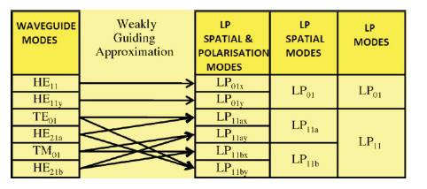
Figure 2. Relation between the LP modes and the real Waveguide Modes He11x , He11y , TE01 , TM21a , HE21a , and He21b of the six-mode FMF
LP11a and LP11b are used to distinguish the degenerate LP11 mode, and the suffix x and y in the indexes are used to distinguish the two orthogonal linear polarizations.
The six-mode FMF allows for six independent data channels to be simultaneously transmitted at a single wavelength. The six data channels are launched and the polarization multiplexed into the LP01 , the LP11a, and the Lp11b spatial mode, using a mode multiplexer with high mode selectivity (> 28dB). The mode multiplexer is based on phase masks fabricated in glass, which is a simple yet effective alternative to multiplexers based on programmable spatial light modulators.
The design offers low crosstalk and low polarization dependence. After transmission, a second mode multiplexer is used to separate the received optical field into three spatial channels that are detected by three synchronized coherent receivers with polarization diversity.
In order to recover the transmitted data, 66 MIMO DSP is applied to undo coupling effects occurring within the fiber. MIMO processing compensates linear impairments like dispersion, crosstalk, and DGD between modes and polarizations.
The FMF used in this work is based on a depressed cladding index profile with normalized frequency V ≈ 5, where the normalized frequency is defined as 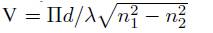 where d is the core diameter, λ the wavelength of light, and n1 and n2 are the refractive indices of core and cladding, respectively.
The fiber was designed to guide exactly six polarizationand spatial-modes (The fundamental LP01 mode and the twofold degenerate LP11 mode), and also to minimize the modal DGD between the LP01 and LP11 across the C- band.
The DGD has to be kept as small as possible, because any delay introduced between the SDM channels has to be compensated by means of filters with a correspondingly large memory as part of the MIMO DSP.
The fiber employed in the experiment [12] has a loss coefficient of 0.205 dB/km at 1550 nm and no significant mode. The effective areas of the LP01 and LP11 modes are approximately 155 and 159 km2 respectively, and the chromatic dispersion is 18 ps/(nm km) for both LP01 and LP11 modes.
The DGD between the LP01 mode and the LP11 mode is to be measured by launching a 100-ps intensity-modulated probe pulse simultaneously into the LP01 and the LP11 spatial mode, and its value measured for a 96-km long FMF was found to be within 2.6 ± 0.1 ns over the wavelength range of 1530 to 1565 nm, corresponding to a length specific DGD of 27 ps/km dependent loss.
In comparison, the DGD of a Step-Index (SI) profile, FMF with the same normalized frequency is 4300 ps/km, and therefore more than two orders of magnitude larger. Fiber with DGD even lower than 27 ps/km are highly desirable in order to further reduce the memory size required in the MIMO DSP.
In order to achieve the maximal SDM capacity gain, the complete set of modes supported by the 6-mode FMF has to be launched without significant crosstalk [18]. We therefore built spatial-mode multiplexers (MMUXs) to couple the light from three single-mode fibers into the different spatial modes of the 6-mode FMF.
A simple way to selectively couple light into a LP 11 mode [21-22], where a phase plate having a phase profile matching the phase of the target mode is inserted into the optical path between the incoming SMF and the 6-mode FMF.
The theoretical phase and intensity profiles of the Linearly Polarized (LP) spatial modes of a 6-mode FMF are shown in Figures 3(d) and 3(c). The LP01 mode (first column in Figure 3) has a flat phase front and can, therefore, be directly coupled into the six-mode FMF from the output of an SMF. Coupling into the LP11 mode requires a phase plate that introduces a phase jump between two half planes.
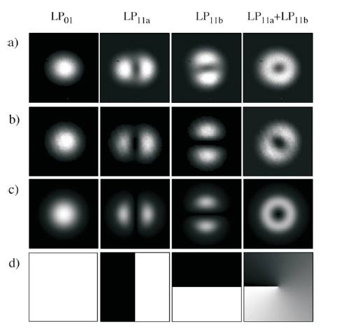
Figure 3. Mode Intensity Profiles measured after a) 96-km and b) 33-km 6-mode FMF for different Launched Modes. c) Theoretical Mode Intensity profiles for a 6-mode FMF and d) Corresponding Phase Profiles
Two orthogonal orientations for the half planes are possible as indicated in columns 2 and 3 in Figure 3, and are denoted as LP11a and LP11b respectively. The LP01 mode, does not require a phase plate and can be directly coupled into the FMF.
The coupling efficiency ηnm describing the coupling between a SMF and a corresponding LPnm mode of the FMF can be calculated using the overlap integral [23]
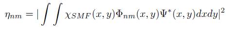
where ΧSMF is the normalized complex amplitude produced by the SMF on the facet of the FMF, and where the normalization
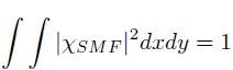
is used. The optimum coupling efficiency ηnm is found to be nearly 0 dB for the LP01 mode whereas it is close to 1 dB for the LP11 mode.
Multiple modes can be excited simultaneously by using beam splitters as shown in Figure 4. The MMUX in Figure 4 has three ports consisting of 3 collimators with a Full Width Half Max (FWHM) beam diameter of 500 μm.
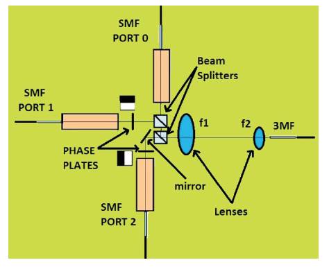
Figure 4. Schematic setup of the 6-Mode FMF mode Multiplexer (MMUX)
The light from port 0 is directly coupled into the LP01 mode of the 6-mode FMF, and port 1 and 2 have orthogonal phase plates inserted in their optical path and will excite the Lp11a and LP11b spatial modes, respectively. A double telecentric imaging system formed by a lens pair with focal lengths f1 =75 mm and f2 =3.9 mm, respectively, is used to image the phase plates on the facet of the 6-mode FMF.
The phase plates are fabricated from a Borosilicate glass substrate with a thickness of 0.7-mm, by a photolithographic process followed by an etching process. The resulting thickness difference d necessary to produce a phase difference of π is given by,
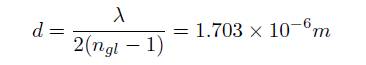
where ngl = 1.455 is the refractive index of the Borosilicate glass.
The beams from the three collimators are then combined using two beam splitters with a reflectivity of 0.50 and a transmittance of 0.38. For this arrangement coupling losses of 9.6 dB, 9 dB, and 7.8 dB are measured for the LP01 , Lp11a , and LP11b spatial modes, respectively.
Note that with an optimized splitting ratio of the splitters and ideal optical components, the predicted minimum loss for the coupler is 5.5 dB. The modal crosstalk of the MMUX was measured using a pair of MMUXs connected by a short (2- m) 6-mode FMF such that mode coupling inside the fiber can be neglected. A crosstalk suppression from the LP01 spatial mode to the LP11 spatial mode of > 28 dB was measured.
Also the mode intensity profiles were measured at the end facet of the 6-mode FMF using an InGaAs infrared camera after 33 and 96 km of fiber. The results are reported in Figures 3(a) and 3(b), respectively. The measurements after 33 km FMF are in good agreement with the corresponding simulated intensity profile reported in Figure 3(b), whereas after 96 km, the images become blurry because of crosstalk between the modes.
This was also confirmed by measuring the crosstalk of the MMUX pair interconnected by 33 and 96 km of FMF, where a crosstalk fluctuating around -18dB and -11dB, respectively, was observed. Even if the noticeable crosstalk in Figure 3(a) is small, the crosstalk produces a significant transmission penalty if left uncorrected.
The SDM transmission-measurement setup is shown in Figure 5. The source signal for the experiment is generated by modulating an External Cavity Laser (ECL) at 1560-nm wavelength and having a linewidth of 100 kHz. The signal is modulated by a double-nested LiNbO3 Mach-Zehnder modulator using Quadrature-Phase-Shift-Keying (QPSK) where the In-phase (I) and Quadrature (Q) components are driven by two independent De Bruijn Bit Sequences (DBBS) of length 212, respectively [24].
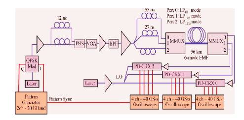
Figure 5. Experimental setup. VOA: Variable Optical Attenuator, PBS:Polarization Beam Splitter, QPSK-Mod: QPSK Modulator, BPF: Bandpassfilter, LO: Local oscillator, PD-CRX: Polarization-Diversity Coherent Receiver
The use of two independent bit patterns offers the advantage of avoiding correlation effects [25-26]. Subsequently, a polarization-multiplexing stage with a delay of 12 ns generates a PDM-QPSK signal which is followed by a noise - loading section consisting of a Variable Optical Attenuator (VOA) in front of an Erbium- Doped Fiber Amplifier (EDFA).
The PDM-QPSK signal is then split into three copies with a relative delay of 27 ns and 53 ns, that are connected to different SMF ports of the input MMUX. The MMUX is connected to the FMF fiber under test and a second MMUX acting as mode demultiplexer is used to terminate the FMF. The mode demultiplexed signals are then amplified using low noise EDFAs before being detected by three Polarization-Diversity Coherent Receivers (PD-CRX).
Each PD-CRX consists of a Polarizing Beam Splitter (PBS) followed by two optical hybrids whose output ports are terminated by four balanced receivers. A second ECL is used as a Local Oscillator (LO) and the resulting 12 electrical high-speed signals from the PD-CRXs are captured using 3 high-speed digital oscilloscopes with 4 ports each, operating at a sampling rate of 40 GS/s. Each measurement consists of a total of four million samples captured using a common trigger signal.
The measurments are subsequently analyzed using off-line DSP. The 6x6 MIMO DSP architecture is an extension of the 2x2 implementation frequently found in coherent PDM receivers and are shown in Figures 6 (a) and (b). The six complex received signals r1-6 derived from the 12 electrical signals from the three PD-CRXs are fed into six column equalizers (ceq1-6 ) (Figure 6(a)). Each of the column equalizers produces a single output signal y1-6 .
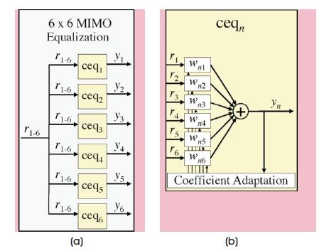
Figure 6. a) Architecture of the MIMO Equalization Block. b) Architecture of a Column Equalizer ceqn
The architecture of the column equalizer ceqn is reported in Figure 6 (b) and contains six Feed-Forward Equalizers (FFEs). Each FFE has L taps associated with the complex coefficient vectors wn1-n6 with length L. The recovered signal yn is determined as the sum of the outputs of the 6 FFEs. The 6x6 MIMO DSP requires a total of 36 FFEs and the equalizer coefficients wn1-n6 are optimized by applying the Least- Mean Square estimate (LMS) algorithm [27] modified to include Carrier Phase Estimation (CPE) based on the fourth power algorithm [28].
In order to achieve initial convergence of the equalizer coefficients, the algorithm assumes knowledge of the received data (data aided) for the first 5,00,000 symbols, and later switches to a decision-directed LMS algorithm. Finally the Bit-Error Rate (BER) is evaluated over the last one million bits of the acquired data.
Figure 7 shows the experimental BER curves after off-line 6x6 MIMO processing with 120 taps, after transmission through 96 km of 6-mode FMF. All 6 transmitted data streams are successfully recovered by the MIMO DSP. The BER curves are plotted as a function of OSNRpol , which is defined like the single-mode OSNR (using 0.1-nm optical noise reference bandwidth), but only the noise that is copolarized with the corresponding signal component is included. Figure 7 also shows the theoretical limit for coherent detection of QPSK, and the Back-to-Back (B2B) measurements as a reference.

Figure 7. BER curves for 6-channel PDM-SDM Transmission of 20-Gbaud QPSK over 96 km of 6-mode FMF. (Also shown for reference are the backto-back measurements and the theoretical limit).
All B2B measurements show a penalty of less than 0.8-dB at a BER of 10-3 , and all 6 BER curves of the transmitted signals are within 1.2 dB from the Back-to-Back measurements. This excellent performance shows that crosstalk present in 96- km of 6-mode FMF can be successfully compensated with a very low impact on system performance.
Figure 8 shows the BER when 2x2 and 4x4 MIMO DSP is used. The performance is dramatically degraded. A large penalty of 8 dB at a BER of 10-3 is observed for the Lp11 mode, whereas a BER of 10-3 cannot be reached for the LP01 mode. Also we observe a large variability of the BER for different values of OSNRpol , which we attribute to the fact that for each OSNRpol setting, measurements are taken several minutes apart from each other. Therefore, the crosstalk conditions, which are continuously changing in the fiber on a millisecond time scale, may have been different, leading to a variation in BER. Also, the authors would like to mention that this result is only valid for the low- DGD six-mode FMF used in this experiment. For FMF with larger modal propagation constant difference Δβ, a weaker coupling between the LP11 and the LP01 modes is predicted, and good performance can be expected.
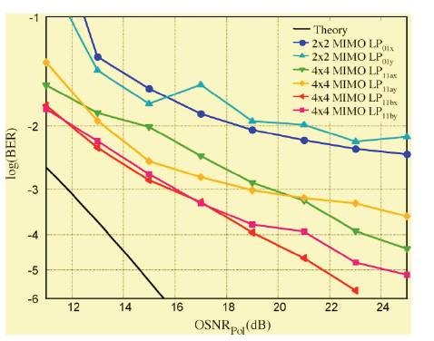
Figure 8. BER Curves for 96 km of Six-mode FMF obtained by applying 22 MIMO DSP for the LP mode and 44 MIMO DSP for the LP mode
MIMO DSP techniques were applied to nullify linear distortions and crosstalk introduced by the FMF. In this section, MIMO DSP techniques are used to estimate the linear transfer function of the FMF channel. The 6-mode FMF is equivalent to a 6x6 MIMO channel, which is fully characterized by its 6x6 impulse responses hnm , where n is the index of the receive port and m is the index of the transmit port.
The squared magnitude of the 6x6 impulse responses are shown in Figure 9 for the 96-km long FMF. In this representation, each column corresponds to the impulse responses associated to a particular transmit port, whereas each row is associated to a particular receive port.
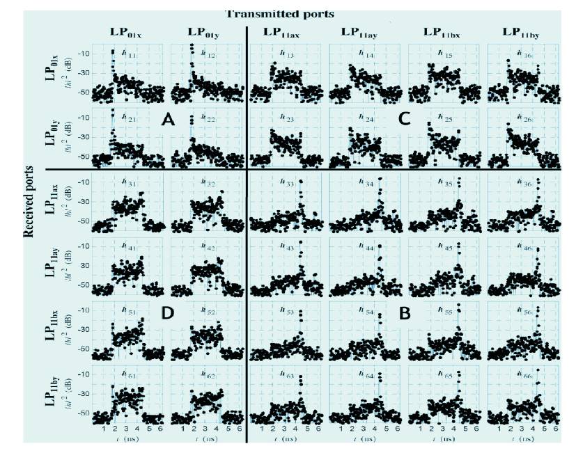
Figure 9. Squared magnitude of the PDM-SDM 66 impulse responses for 96 km of six-mode FMF.
The determination of the impulse-response matrix is referred to as channel estimation in MIMO literature, and several algorithms are available [28]. The results presented in Figure 9 were obtained using a Least-Square-Error (LSE) estimator [11].
In order to highlight the components of the impulse response due to mode coupling, chromatic dispersion of 96x18 ps/nm was electronically compensated on the received signal ri(k) prior to estimating the impulse-response matrix. This allows to clearly identify the main coupling which appears as sharp peaks.
Figure 9 is divided into four regions identified as A, B, C, and D.
Region A consists of a 2x2 array located in the top left corner and is formed by the impulse-responses h11 , h12 , h21 , and h22 . Region A shows the coupling between the two polarizations of the fundamental mode (LP01 ).
Region B consists of the 4x4 array located on the bottom right corner and, comprising the impulse-responses h33 , h36 , h63 , and h66 . Region B represents the coupling between the spatial and polarization modes LP11a , and LP11b .
The remaining off-diagonal regions C and D, which are enclosed by (h13 , h16 , h23 , h26 ), and (h31 , h32 , h61 , h62 ), respectively, describe the crosstalk between LP01 and LP11 modes. In Figure 9, strong coupling peaks appear in regions A and B, and typically 100 to 1000 times weaker, 2.6-ns wide distributed coupling is observed in regions C and D.
The width of the distributed coupling of regions C and D is consistent with the DGD of 96-km 6-mode FMF, and can be interpreted as coupling occurring at various locations along the fiber. In fact, because light traveling in the faster LP01 mode will arrive earlier than the light traveling in the slower LP11 mode, the time of arrival can be used to predict the location of the coupling between LP01 and LP11 modes.
Note that also regions A and B show a weak distributed coupling next to the strong coupling peaks. This weaker distributed coupling represents light that couples back and forth between LP01 and LP11 or LP11 and Lp01 modes, respectively.
Figure 9 also confirms the excellent alignment of the MMUX. Any misalignment in the phase plates would be immediately visible as narrow crosstalk peaks either at the beginning or at the end of the distributed coupling in regions C and D.
The impulse response matrix provides a clear picture of the MIMO channel, indicating location and amount of crosstalk introduced by the MMUX and the 6-mode FMF. It is therefore a very useful tool for fiber characterization, coupler optimization, and fault localization.
In this review paper, it is inferred that SDM transmission is possible in both multi-mode and multi-core fibers based on Multiple Input Multiple Output (MIMO) Digital Signal Processing (DSP) systems. The results confirm that long haul transmission over both these fibers exist even in the presence of the enhanced significantly large crosstalk between the SDM channels. Here, we also demonstrated single-wavelength as well as 6-channel spatial- and polarization-mode-multiplexed transmission of 6x40-Gb/s QPSK signals over 96-km of FMF with less than 1.2-dB penalty. The impulse-response matrix of the low-DGD FMF was described, revealing in detail the coupling between the six guided spatial and polarization modes. The results were obtained using offline coherent MIMO DSP and highly efficient mode couplers based on phase plates.