(1)
Attenuation of sound is the process of decay in the amplitude due to combination of absorption and scattering. Transmitted pulse is influenced by many factors for selecting the center frequency of active sonar. For example, for a fixed size transmitter array with constant radiated power, ambient noise decreases with frequency and the source level increases with frequency. These considerations would suggest the use of high center frequency. On other hand the absorption of the medium increases with frequency. Here, in this paper the relationship between the range and optimum frequency is derived which helps in selecting the center frequency.
Adaptive SONAR (Sound Navigation and Ranging) systems have many similarities to radar and electro- optical systems. The process of sonar is based on the propagation of sound waves between a target and a receiver. The main purpose of sonar is the detection or classification (estimation of position, velocity, and identity) of submerged, floating, or buried objects. The nature of the required object, known as the sonar target, depends on the application. Examples include man-made objects of military interest (a mine or submarine), shipwrecks (as a navigation hazard or archaeological artifact), and fish (the target of interest to a whale or fisherman). In military applications, sonar systems are used for detection, classification, localization, and tracking of submarines, mines, or surface contacts, as well as for communication, navigation, and identification of obstructions or hazards (e.g., polar ice). In commercial applications, sonar is used in fish finders, medical imaging, material inspection, and seismic exploration [2].
The two most common types of sonar systems are passive and active. Passive sonar includes a receiver but no transmitter. The signal to be detected is then the sound emitted by the target. In an active sonar system, waves propagate from a transmitter to a target and back to a receiver, analogous to pulse-echo radar. In addition to these two types, there is also daylight or ambient sonar, where the environment is the source of the sound, which bounces off or is blocked by the target, and the effects of which are observed by the receiver. This latter type of sonar is analogous to human sight [1].
Active sonars know more about the signal to be detected, and therefore the receiver is designed to match the signal, i.e., it uses matched filter processing. But the background against which the signal has to be detected, contains reverberation in addition to the ambient and self-noise of passive sonars. This additional background is all important in active systems and the designer must be aware of its magnitude and how to discriminate against it. Active sonars employ two broad classes of pulse types. Continuous Wave (CW) is a pulse of constant frequency and duration T seconds. The bandwidth of the pulse, and of the matched filter for optimum detection of this pulse, is 1 /T Hz. Frequency Modulation (FM) is the frequency of the pulse changes during the T second's duration of the pulse. The bandwidth, B, is not now the inverse of the pulse length [3].
So, the target detection of active sonar is difficult in the presence of reverberation. Reverberation is mainly due to multiple reflections of the transmitted signal by the ocean surface, ground, and volume. To achieve a good performance against reverberation, the optimum center frequency must be designed to maximize reverberation rejection. By choosing proper optimum center frequency we can reduce the effect of reverberation on the transmitted signal.
Here, this paper gives a quick review about the echo excess equation[4]. Section 1 presents how center frequency is derived using echo excess equation. It also deals with how reverberation and own-ship is effected by optimum center frequency in section 2. Finally, the results of selecting center frequency are shown.
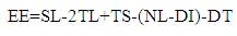
The process of decay in amplitude due to a mishmash of absorption and scattering of sound is known as attenuation. The term ''absorption'' implies exchange to some other form of energy, usually heat, while ''scattering'' implies a redistribution of energy in angular direction away from the original propagation direction, with no overall loss of acoustic energy. The rate of attenuation of sound inside the water is less than that in the air, where as it will be larger in case of electromagnetic wave propagation in water than that in the air. Low-frequency sound, can travel for thousands of kilometres, but high-frequency sound is attenuated more quickly. In active sonar desired values for probability of detection(PD) and probability of FA (Pfa) are specified. These PD and Pfa values are used to find the value of S/N necessary at the output of the processor by means of a set of ROC curves. The processor consists of an array of sensors, a beam former and a correlation receiver. The output of the processor is compared with a threshold value to determine whether a signal is present or not. The S/N in dB at the output of the beam former is called the detection threshold (DT). For the background noise limited case Echo excess (EE) in dB in 1-Hz band is given by
The source level is defined by SL = 171.5+ 10 log10 P +DIt where It is directivity index of the transmitter array, P is radiated power in watts and DI is S/N at the output of the beam-former to the S/N at a single sensor. TL is transmission loss, TS is target strength, NL is background Noise, DI is directivity index of the receiver array, and DT is detection threshold.
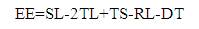
For the reverberation on noise limited environment,
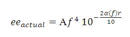
EE without logarithm is given as follows

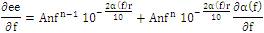
The selection of centre frequency used for the transmitted pulse is influenced by different parameters. For instance ambient noise decreases with frequency and source level increases with frequency for a fixed-size transmitted array with steady radiated power. These considerations would suggest the use of a high centre frequency. On the other hand, the absorption of energy increases with frequency. As a result, it is possible to find a optimum centre frequency that maximises the echo excess in eqn. (3) with respect to frequency.
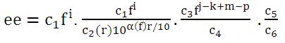
The frequency dependencies for the factors in eqn. (3) is written as
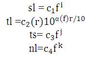
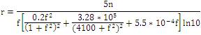
(r is in Kilo Yards, f is in KHz), is a frequency self-governing spreading loss. The absorption loss α(f) is estimated and is given below:
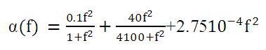
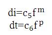
Where, α is in dB per Kyd and f is in KHz. Substituting eqn.(5) in eqn.(4) gives
The following assumptions to acquire values for the exponents of 'f 'in eqn.(7) are made as
i = 2, fixed size transmitter array with constant radiated power,
j = 0, TS constant
k = -2, ambient noise spectrum
m = 0, DI of receiver is self-governing of frequency.
P = 0, receiver gain is independent of frequency.
The choices of above values are based on:
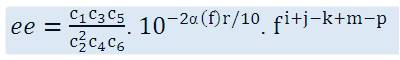
Then
Where
After simplification

Where, r is in kilo yards, f is in KHz [4-5].
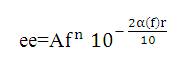
For a required range, the loss in performance is calculated which is related to the values as determined by (24). Considering i = 2, k = -2, j=0, m=0, p=0, n=4 then excess echo is specified by
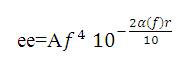
Figure 3 is plotted by assuming a desired range of 100Kyds, f = 1500Hz.
then
Let A =1, eeactual is calculated then eeloss= (eeactual - ee) is found out at every frequency, and eeloss vs. frequency is plotted which is shown in Figure 3.
In a reverberation noise limited environment, suitable expression for ee is used and the frequency dependence of  is also included. This dependence is a function of the type of reverberation noise (surface, volume, or bottom) encountered.
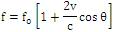
The velocities of scatterers are assumed to be samples of a zero mean random process so that the returns from these scatterers are centered at zero frequency in the absence of platform motion. These returns must be arranged some times to be centered at a fixed frequency in the occurrence of platform motion, in spite of the direction of transmitted beam. The function that removes the component of Doppler shift due to platform motion is called own-ship Doppler nullification. Assuming that a signal with a centre frequency f0 is sent, the received component due to reverberation noise form surface or volume scatterers is centred at

To enter the reverberation noise at frequency, for all beam directions, the centre frequency to be a function of the beam direction is arranged.
For a required range, the loss in performance is calculated by using the values i = 2, k = -2, j=0, m=0, p=0 i.e. n=4 and assuming a desired range of 100Kyds, f as 1500Hz. After substituting these values in eqn.(8), we can find eeactual and let A=1. Then eeloss= (eeactual - ee) is found out at every frequency, and eeloss in dB vs. frequency is plotted which is shown in Figure 1.
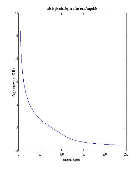
Figure1. Optimum centre frequency as function of range.
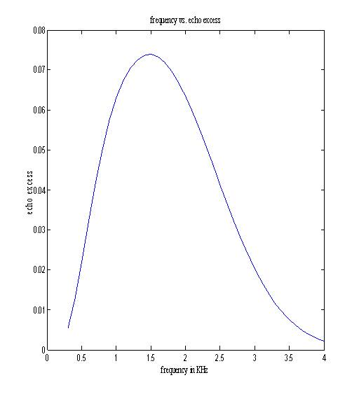
Figure 2. Echo excess as a function of centre frequency
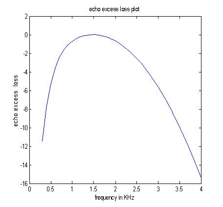
Figure 3. Reduction in echo excess as a function of centre frequency (range=100 kyds).
Thus, from Figure 1 it is clear that low values of centre frequency are required for long-range active sonar operation. Figure 2 shows variation of echo excess with the frequency. This shows that echo excess decreases after the optimum centre frequency. Figure 3 illustrates the reduction in ee as function of frequency. The optimum value of centre frequency for 100Kyds is obtained from Figure 3. By choosing the optimum centre frequency, the effect of reverberation can be reduced on active sonar.