(1)
The design of Infinite Impulse Response (IIR),basically are of two types. In literature ,one is Butterworth and second one is Chebyshev. Digital IIR Filters are derived from analog IIR Filters by different Laplace(S) to Z –Transformation techniques, out of which the most efficient techniques are differentiation approximation, Al-aloui and bilinear transformations. In the proposed paper, an attempt is made to develop digital IIR Lowpass, high Pass and band pass filters from novel S-Z transformations which will be derived from Finite Impulse Response (FIR) windows. The performance of the proposed S-Z Transformation is verified by the comparison of differentiators.
Various new classes of s-to-z transformations have recently been proposed [1, 2]. The principle for these classes are discrete in time low-order differentiators which can replace the Laplace parameter s in continuous-time transfer function H(s) in order to derive the discrete-time equivalent transfer function. These are also used in designing discretetime proportional–integral–differential controllers. In this brief, we shall focus on three classes, those are the secondorder differentiators suggested by Al-Alaoui [1] and the first & second order differentiators proposed by Pei and Hsu [2] . Our primary aim is to propose a closed-form expression for the elements of each class. Later, we show that individual element of each class obeys a particular property: The imaginary component of its frequency response is closer to the ideal value. Final step is to show that these classes can connect to all-pass IIR fractional lag filters, allowing another parameterization for these differentiators. A comparison for the proposed s-to-z transformations is finally presented.
FIR filters applications are based on the window functions [3-8], one of the filter characteristics is attenuation in stop band and allows the signal in pass band. Basically the filter characteristic is how efficiently it attenuates the unwanted signals in unwanted frequency region. Basing on Fourier Transform, FIR window filters are of the characteristics having fixed unwanted frequency region for fixed window.
Window based differentiator and Integrator is proposed as in equation (5) from which digital IIR low-pass filters are derived through Butterworth, Chebyshev-I, Chebyshev-II.
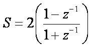
The general expression of the resulting s-to-z transforms for Bilinear Transformations is
The general expression of the resulting s-to-z transforms for Differentiation Approximation is

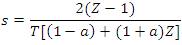
The general expression of the resulting s-to-z transforms for Al-Aloui Operator is
The general expression of the resulting s-to-z transforms. Pei And Hsu Differentiators is
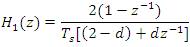
The proposed relation between s-z transformation is based on Fractional Fourier Transform (FrFT)[ 9-13 ] which leads to result in the below equation.

Where
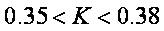
But here the authors have chosen the k value is 0.375 which leads to

For these values better differentiator results are observed in the output graph
On Comparing results for different closed-form expressions for differentiator design using matlab programming, the finally observed graph shows that the proposed technique results lies in between Old Al-Alaoui and new Al-Alaoui.
The objective for IIR filter design is to determine both numerator and denominator of the filter coefficients to satisfy filter specifications such as gain pass band and stop band attenuation, as well as cutoff frequency/frequencies for the band pass, band stop, low pass, and high pass filters.
IIR filters can be designed using different techniques. The most common among them is via the reference analog prototype filter. This method is the best designing approach for all standard filters such as low-pass, high-pass, bandpass and band-stop filters. Figure 1 shows the comparison of proposed differentiator. which Al-aloui and other differentiators with Al-aloui and other differentiators.
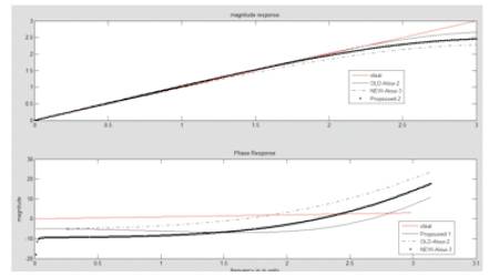
Figure 1. Comparison of proposed differentiator with Al-aloui & other differentiators
The transfer function of IIR filter is a ratio of two polynomials of complex variable z-1. The numerator term provides the location of zeros, and the denominator term provides location of poles of the resulting transfer function of IIR filter. When designing a digital filter as an approximation of a continuous time filter, the frequency response (both amplitude and phase) of the digital filter can be made to match the frequency response of the continuous filter at frequency ωo. The continuous-time filter is minimum- phase if, zeros of its transfer function are observed in the left half of the complex s-plane. A discrete-time filter is minimum phase if, zeros of its transfer function are observed inside the unit circle in the complex z-plane. Then the same mapping property assures that the continuous-time filters that are having minimum phase are converted to discrete-time filters that preserve that property of being minimum-phase.
The Z-transform is applied upon discrete-time signals. It converts a discrete time-domain representation into a complex frequency-domain representation. It is very suitable for analyzing discrete time-domain signals and systems as well. The z-transform is derived from the Fourier discrete time-domain transformation and is considered as the basic operation in digital filter design process.
The Butterworth filter is a signal processing filter which is designed to have a flat frequency response as much as possible in the pass band. It is also known as a maximally flat magnitude filter.
An ideal digital filter should not only completely stop the unwanted frequencies, but should also have the uniform sensitivity for the wanted frequencies. But practically such an ideal filter cannot be achieved, but Butterworth has provided that successively closer approximations were obtained with increasing numbers of filter elements of the right values. Figure 2 illustrates the comparison of the proposed Butterworth filter with Al-Alaoui and Differentiation and Approximation filter types.
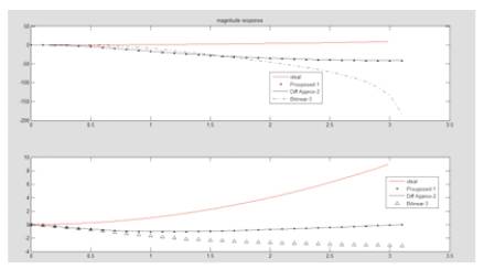
Figure 2. Comparison of proposed butterworth filter with Al-aloui & other filters
A Butterworth filter provides monotonically changing magnitude function with change in Angular frequency ω, unlike other filtering techniques that can have nonmonotonic ripple in pass band and/or the stop band.
Chebyshev filters have the property to minimize the error between the idealized filter and the actual filter characteristic for the filter range, but it provides ripples in the pass band. Chebyshev filters are the type of analog or digital filters which are having a steeper roll-off and also more pass band ripple for type I or stop band ripple for type II chebyshev filter when compared to Butterworth filters. Because of the inherent pass band ripple in Chebyshev filters, the ones which have a smoother response in pass band but a more irregular response in the stop band are desired for only some applications.
Type-I Chebyshev Filters are the most common Chebyshev filters. The gain (or amplitude) response is a function of angular frequency w of the nth-order low-pass filter which is equal to the absolute value of the transfer function.
The pass band for Type-I Chebyshev Filters exhibits equiripple behavior, where ripple factor ε determines the ripple present. In the pass band, the Chebyshev polynomial changes between -1 and 1 so that the filter gain will change between Maxima at G = 1 and Minima at 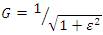 At the cutoff frequency ω0 the gain again takes the value
 but as the frequency increases it continues to drop into the stop band
 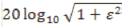 so that a ripple amplitude of 3 dB results from ω=1.
Figure 3 illustrates the comparison of the proposed Chebyshev-I Filter compared with Al-Alaoui and Differentiation and Approximation filter types
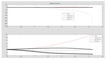
Figure 3. Comparison of proposed Chebyshev filter with Al-aloui & other filters
Based on equation (5) the proposed differentiator for K=0.375 is shown in Figure 1, where upto 1.8 nyquist frequencies follow with the ideal differentiator and is better than new Al-aloui3 which is derived from equation(3). Butterworth & Chebyshev-1 low-pass filters are derived from the proposed differentiators are shown in Figure 2 & Figure 3 respectively. The obtained filter characteristics show small errors in comparison with the remaining filters and also its having low transition width. In similar lines, it will be extended for future work to implement filters for different values of k.