When the errors introduced by the information channel are unacceptable, then channel coding is needed. The use of channel coders with source coders provides efficient and reliable transmission in the presence of noise. Coding permits an increased rate of information transfer at a fixed error rate, or a reduced error rate for a fixed transfer rate. A convolution coder accepts a fixed number of message symbols and produces a fixed number of code symbols, but its computations depend not only on the current set of input symbols but also on some of previous input symbols. [1] Through this paper, we have illustrated design of convolution encoder using time domain approach with VHDL platform. The target technology used Is Sparten FPGA device.
Convolution code was introduced in 1955. In convolutional code, the block of n code digits generated by the encoder in a particular time limit, depends not only on the block of k message digits within that time unit but also on the data digits within a previous span of N-1 time unit (N>1). For convolutional codes, k and n are usually small. Convolutional codes can be devised for correcting random errors, burst errors or both. Encoding is easily implemented by shift registers [2].
The time domain behavior of a binary convolution encoder with code rate 1/M may be defined in terms of set of M impulses response. The simple encoder of Figure 1is having code rate ½.Hence,we need two impulse responses to characterize its behavior in the time domain. Let the sequence [g01 , g11 ,……, gx1 ]{Here ,x represents the number of points from where bits are extracted for modulo-2- adders}denotes the impulse response for path p1 and the sequence [g22 , g22 ,……, gx2]denotes the impulse response of path p2.There two impulse responses are obtained by determining the two output sequences of the encoder that are produced in response to the input sequence (1,0,0,…..).The impulse response so defined is called the generator sequence of the code.
Let (d0, d1, d2,…..) denote the message sequence that , enter the encoder of Figure 1 one bit at a time (starting with d0).The encoder generates the two output sequence, denoted by [Ci1 ] and [Ci2 ],by convolving the message sequence with the impulse response of path p1 and p2 respectively. Thus, the output sequence of path p1 is defined by
Convolution sum:

Where, di-1=0 for all l >i
Likewise, the output sequence of path P2 is described by

After convolution, the two sequences [Ci(1)] and [Ci(2)] are combined by the multiplexer to produce the encoder output sequence [Ci], as shown by

The following example illustrates the steps to obtain control bits in convolution code.
The sample impulse responses are considered.
Impulse response of path P1 is

And Impulse response of path P2 is

Note that the generator sequence or impulse response is directly obtained from the circuit diagram (Figure 2) of encoder. '1' is representing a 'connection' and a '0' is representing 'no connection' with the modulo-2 adder determining the sequence for that path.
Let the incoming message sequence be as follows:

Then, the use of equation (1) yields the following values for the elements that constitute the path P1 output sequence:

Hence the output of path P1 is
Similarly, equation (2) yields the following output for path P2,

Hence the output of path P2 is
Finally, multiplexing [Ci(1)] and [Ci(2)], we get the encoded output, sequence as

Note that the message length k=5, which produces M(K + L – 1) = 2( 5 + 3 – 1) = 14 bits output sequence.[4]
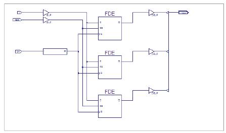
Convolution Encoder state machine methodIn this section RTL (Register- Transfer Level) for above example obtained by coding in VHDL as shown.
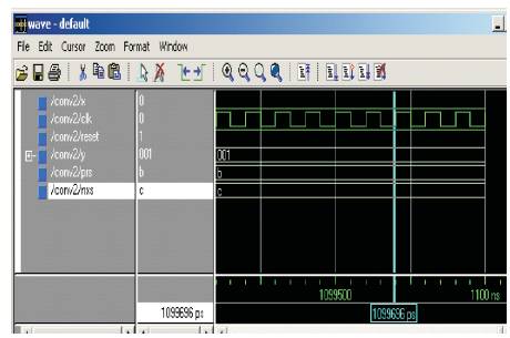
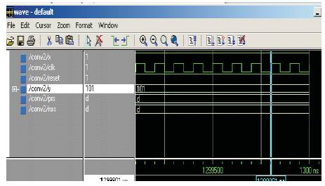
Simulation results are also given so as to get verification.

Figure 1. Simple Encoder

Figure 2. Code Tree
Example for state machine
Input message is 1101 k = 4
The constraints length of encoder, L = 3 and M = 3

Now, 2 zeros are required to be padded so that the input message scrolls completely through the encoder.
Message entering encoder is 110100
This message follows following states.

The encoded code is [C] = [111, 110, 010, 100, 001, 011].[4]
Results for state machine are shown in Figures 3, 4 and 5.1, 5.2, 5.3, 5.4, 5.6

Figure 3. Convolution Encoder State Machine Method

Figure 4. Encoder State Machine Design

Figure 5.1 Simulation Result


Figure 5.2 Simulation result

Figure 5.4 RTL

Figure 5.5 Experimental Result

Figure 5.6 Experimental Result
Convolution encoder can be designed for various impulse responses for n no. of bits using time domain method.. For single bit input, multi bit output sequence can be generated and is specially useful when large BW is acceptable.