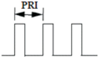
Figure 1. Pulse Modulation Structure of Uniform PRI
In radar, uniform side lobe pattern is useful for detection of weak targets. Important radar characteristic function, i.e., ambiguity function, a two-dimensional function of time delay χ(τ,fd) and Doppler frequency that portrays the distortion of a returned pulse induced by the receiver matched filter due to the Doppler shift of the return radar signal from the moving target, is useful for identification of poor targets. Nonuniform PRI LFM (ascending and descending order) with length 11 as well as uniform Pulse Repetition Interval LFM with length 11 has been considered here. The ambiguity diagram, which defines the radar's precision, is used to quantify PSLR (Peak Side Lobe Ratio) and ISLR (Integrated Side Lobe Ratio). To minimise side lobes, this paper proposes a new paradigm for PCW (Pulse Continuous Wave) and LFM signals. Several applications are discussed that are specifically related to the strengths and limitations of nonuniform PRI waveforms.
Radar needs a large peak signal power to average power ratio at the time of the target's return signal ( Skolnik, 1980). Waveform design plays an important role for range, velocity resolutions measurement for different radar and sonar applications. Pulse compression technique is employed in radar for good detection and range resolution. A uniform side lobe level represents an optimum performance. There are significant differences between Continuous Wave Radar and Pulse Radar in term of noise reduction of received signal. Range resolution is the ability of the radar receiver to distinguish between two or more targets at different ranges. Velocity resolution is the minimal radial velocity difference between two objects travelling at the same range. The ability of a radar receiver to differentiate between two or more targets at varying distances is referred to as range resolution. The difference in radial velocity between two objects travelling in the same range is referred to as velocity resolution.
Sensitivity of the nonuniform PRI waveforms will be increased by coherent integration gain while their high countermeasures resistance will be maintained. It is far more difficult to intercept and characterise such waveforms than it is to do so with uniform PRI waveforms. It is theoretically possible to determine frequencies above the Nyquist rate for the average PRI using nonuniform sampling ( Maier, 1993).
The transmitted signal of radar normally consists of a series of pulses, all of the same length and rectangular in shape, modulated for a perfectly coherent carrier. The pulse width is the measurement of how long a pulse lasts. The pulse repetition interval is the distance between successive pulses. The signal model waveforms of uniform and nonuniform PRI are shown in Figure 1 and Figure 2, respectively. The graphical representation of Figures 1 and 2 are shown in Figures 4 and 5 respectively.
Figure 1. Pulse Modulation Structure of Uniform PRI
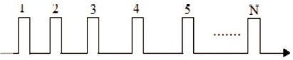
Figure 2. Pulse Modulation Structure of Non-uniform PRI Increasing Order
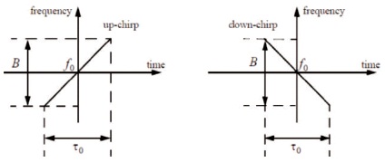
Figure 3. LFM Waveforms: Up-Chirp and Down-Chirp
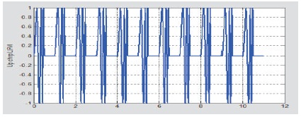
Figure 4. LFM Uniform Pulse Train
Pulse compression is one of the important signal processing technique which is used in radar systems to reduce the peak power of radar pulse by the usage of long especially modulated pulses in order to sacrifice the range resolution associated with a shorter pulse.
Longer pulse are employed at transmitter side and at radar receiver, the matched filter output results in short pulse signals with improved SNR during pulse compression procedure ( Levanon, 2002; Mahafza, 2016).
This pulse compression is widely used in the radar to get higher detection ranges due to increasing the transmitted energy and realization of high range resolution. The advantages of larger range detection ability of long pulse and better range resolution ability of short pulse are achieved by pulse compression techniques. For range resolution, the bandwidth of the pulse is taken into account but not necessarily the duration of the pulse.
where, Rresolution is range resolution; τ is pulse duration; c is velocity of light; B is signal bandwidth.
A uniform PRI waveform acts as a sample of the target return signal and the received pulse sample sequence for one range bin as,
where, UK is the sample corresponding to the Kth pulse, VR is complex voltage determined from system parameters and range bin. fd is Doppler frequency and T is pulse repetition interval.
In the nonuniform waveform, the sequence is,
where, Tk is Kth inter-pulses interval.
With uniform PRI the processing of these samples are straightforward. The Cooley-Tukey algorithm demands that the number of input samples be a square integer in order to maximize computational throughput. The samples are made in the same manner as nonuniform PRI samples are made, except they are now unequally distributed.
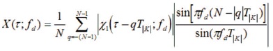
In the same way, evenly spaced samples can be transformed to the frequency domain, and unequally spaced samples can be translated as well. The discrete Fourier transform is used to approximate the spectral content of a series of unequally distributed samples at a given frequency, as follows:
where, fn is test frequency, Uk is Kth data sample, Wk is Kth weight, tk is the instant of the Kth sample.
A single uncompressed pulse cannot usually provide sufficient range resolution or Doppler resolution. Satisfactory range resolution will be reached using pulse compression and acceptable velocity resolution by using a coherent pulse train.
Radar pulse compression has research interest among academicians in the previous few decades. The radar pulse detection system has gone through a lot of testing to obtain low side lobes and strong range resolution. In the past, many pulse compression methods were used but the most common and popular is R.H Dickie's Linear Frequency Modulation (LFM), which he invented in 1945. Pulse compression techniques include Costas codes, binary phase codes, poly-phase codes, and non-linear frequency modulation.
In the methodology presented by Kumar et al. (2011), a combination of the incoming signal and a one-bit shifted version of the incoming signal is subjected to amplitude weighting. To produce cross correlation between the amplitude weighted signal and the combined signal, a matching filter is used. This methodology outperforms all other traditional side lobe reduction strategies in terms of peak side lobe ratio (PSL) and integrated side lobe ratio (ISL). This approach eliminates the large main lobe splitting that is the major shortcoming of the Woo filter and implements it with low signal to noise ratio SNR loss.
Reddy et al. (2013) have obtained experimental data confirming that complementary codes have the best ACF and AF characteristics in comparison to all other codes, decreasing noise levels to nearly zero.
Rawat and Sarate (2014) examined the benefits and drawbacks of LFM, Biphase, and Polyphase Pulse Compression approaches. The mainlobe width, range resolution, and PSL are all significant criteria to consider while determining codes.
Radio frequency carrier signal, usually modulated to capture the required data by the system and pulse modulated carrier utilized in continuous wave systems for simple ranging radars, such as Doppler radar.
The carrier is simply turned on and off in rhythm with the pulses in pulse modulation, the modulating waveform is not present in the transmitted signal, and the envelope of the pulse waveform is recovered from the demodulated carrier in the receiver.
Linear frequency modulation (LFM) is the first and probably still is the most popular pulse compression method. Frequency or phase modulated waveforms can be used to achieve much wider operating bandwidths. In this case, the frequency is swept linearly across the pulse width, either upward (up-chirp) or downward (down-chirp) as shown in Figure 3 ( Levanon & Mozeson, 2004; Mahafza, 2016).
The complex envelope of typical LFM signal is considered for our simplicity as given.
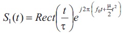
Train of identical Linear Frequency Modulated pulses provides both range resolution and Doppler resolution. The ambiguity function still suffers from significant side lobes, both in range and Doppler. To reduce these side lobes modifications are usually applied ( Levanon & Mozeson, 2004).
The generalized equation for LFM with nonuniform PRI signal is given by Equation (6) and is shown in Figure 5.
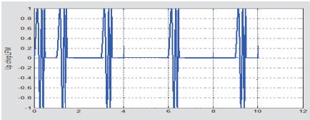
Figure 5. LFM Nonuniform PRI Pulse Train Ascending Order
where, the different PRIs are indexed by the variable k (Tk).
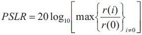
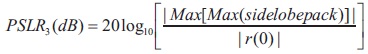
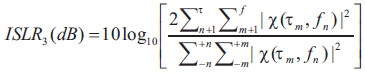
The pulse compression system uses two performance indicators, Peak Side Lobe Ratio and Internal Side Lobe Ratio. PSLR is the ratio of peak side lobe to mainlobe value in decibels. The ISLR is the ratio of total energy in sidelobes to energy in the mainlobe, is another important output metric that is frequently discussed in the literature. Convex combinations of ISLR and PSLR can be used to build objective functions.
The peak side lobe level ratio (PSLR) of matched-filter is a popular method for determining the degree of interference that may be expected from point targets. The matched filter integrated side lobe ratio (ISLR) is used to characterize the amount of interference for volume or surface clutter.
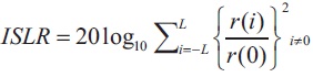
The peak side lobe ratio is usually expressed as a ratio of the peak side lobe amplitude to the main lobe peak amplitude and is expressed in decibels.
This refers to the total energy in all the side lobes and is expressed as a ratio of the total side lobe energy to main peak energy ( Richards, 2014).
PSLR and ISLR in ambiguity domain can be expressed as
Pulse width =0.5 μs
T = 5 μs
Pulse width = 0.5 μs
T=1 μs to 10 μs
Pulse width = 0.5 μs
T = 10 μs to 1 μs
Pulse width = 0.5 μs
T = 5 μs
Pulse width = 0.5 μs
T = 1 μs to 10 μs
Pulse width = 0.5 μs
T = 10 μs to 1 μs
The major goal of this paper is to look into an efficient pulse compression approach that has better (lower) values of Peak Side lobe Level and Integrated Side lobe Level with uniform and nonuniform PCW and LFM PRI sequences.
Next, the minimized ambiguity function of quality factors for PSLR and ISLR are calculated, and the numerical and graphical results are visualized.
The PCW ambiguity plot of uniform pulse train is shown in Figure 6. The PCW ambiguity plot of nonuniform PRI pulse train with ascending order is shown in Figure 7. The PCW pulse train with nonuniform PRI (descending order) is shown in Figure 8.
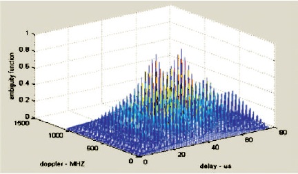
Figure 6. Ambiguity Plot for Uniform PCW Pulse Train
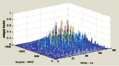
Figure 7. PCW Pulse Train with Nonuniform PRI Ascending Order
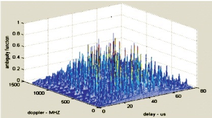
Figure 8. PCW Pulse Train with Nonuniform PRI Descending Order
The LFM ambiguity plot of uniform pulse train is shown in Figure 9. LFM ambiguity plot of nonuniform PRI pulse train (ascending order) is shown in Figure 10. LFM ambiguity plot of nonuniform PRI pulse train (descending order) is shown in Figure 11.
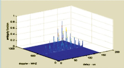
Figure 9. Ambiguity Plot for Uniform LFM Pulse Train
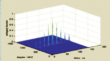
Figure 10. LFM Pulse Train with Nonuniform PRI Ascending Order
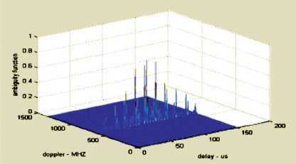
Figure 11. LFM Pulse Train with Nonuniform PRI Descending Order
Computed parameters of both uniform PRI, nonuniform PRI (in ascending and descending order) are shown in Table 1.
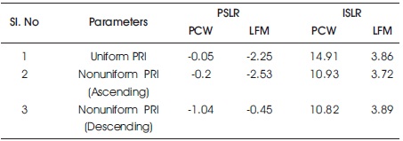
Table 1. Computed Parameters for the Two Methods
Based on the findings, we believe that it has been a very effective pulse compression approach. This approach allows for higher range resolution without the use of highpower transmitters and receivers. Costas codes, Binaryphase codes, non-linear frequency modulation, and other modulation techniques can now and in the future be employed successfully in passive radar systems. The complexity of radar waveforms has gradually increased as the amount of digital signal processing capacity available has steadily increased. First, it enabled standard pulse- Doppler for lookdown radars with Pulse Compressed Medium PRF modes and track-while-scan systems, and then SAR for other air-to-ground modes. With more power, non-uniform PRI can be used in conjunction with coherent integration of pulse-Doppler systems. There are no insurmountable barriers to such a union, as this article has demonstrated and processing only needs suitable amount of power.
In addition to the examination of PCW and LFM signals, the comparison includes uniform LFM and PCW with length 11 and nonuniform with both ascending and descending order with length 11. LFM signal gives better PSLR compared with ISLR in uniform PRI case. A nonuniform LFM pulse train with ascending PRI provides better results with respect to PSLR compared with uniform PRI of PCW and LFM signals. With Nonuniform descending PRI for PCW better PSLR has been obtained but there has been no improvement in LFM signal. Overall, ISLR is better with uniform PCW and LFM only. Clutter rejection is a more difficult challenge to solve, although it can be done for specialized, high-value applications. MATLAB software is used for designing a matched filter based algorithm for pulse compression radar that uses Linear FM.
The moving target path is identified in this paper to see if it follows the predetermined path or not. As a result, we can implement it in hardware using the VHDL programming language in the designing software Xilinx ISE (Integrated Synthesis Environment) on the FPGA platform.