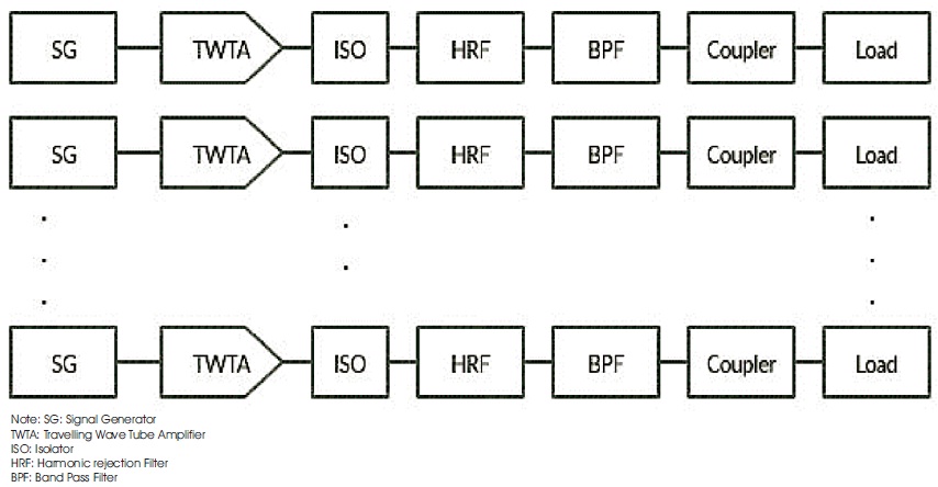
Figure 1. Conventional Block Diagram of High Power Testing
The proposed work presents a new approach of high power testing setup. High power testing is required for all the passive components being used in the payload of the spacecraft. The multi-channel high power testing using conventional approach is more complex. To overcome the issues of conventional approach of high power test, this paper introduces a new approach of high power testing in which two signals can be processed through a single channel using waveguide diplexer. Use of diplexer results in reduction of travelling wave tube amplifier which reduces the complexity and cost of high power testing setup. This paper presents a design of Ku-band diplexer and new approach of high power testing using this diplexer. The diplexer has been designed with 11 GHz and 11.55 GHz center frequencies of pass bands with 30 dB return loss and 0.14 dB insertion loss in both pass bands.
This paper presents a design of the diplexer and new technique of high power test of spacecraft components using that diplexer. Diplexer is a device which is used for splitting and combining two frequency bands. It is the most reduced version of the multiplexer. Diplexer waveguide filters can be used to couple transmit and receive channels to a single antenna (Naeem et al., 2012). This paper presents a design of Ku-band Transmitter-Transmitter type diplexer to reduce the complexity and cost of high power test setup. Similar to the design in Skaik and Abu Hussain (2013), this diplexer also consists of resonators without any external energy distribution networks, hence they are miniaturized in comparison with conventional design.
High power test is required for all passive components being used in the payload of the satellite. In the typical case like multichannel high power test setup being used for the testing of O/P multiplexers; a complex setup is required including large number of TWTAs. It is necessary to reduce the RF power of the test setup by reducing the number of TWTAs to reduce the chance of multipaction during the test (Doshi et al., 2017b). Diplexer is useful to separate RF O/P from a single TWTAs into two required frequency bands. Subramanyam et al. (2014) used individual TWTAs for each channel in the power handling and multipaction test setup which results in complexity. Using waveguide diplexer one can make the setup economical and less complex.
The conventional approach of high power testing is shown in Figure 1. In this method, each signal amplified using individual TWTAs. For the multichannel test setup, it had become very complex. In Doshi et al. (2017b) author described limitation of using high power amplifier which can be reduced by using the TWTAs.
Figure 1. Conventional Block Diagram of High Power Testing
This is general setup of high power testing in which generated signal amplified using TWTAs and HRF, BPF, etc., are used to get specific signal and to remove the unwanted signals from the amplified signal.
The main aim of this research is to reduce the complexity and cost of this high power testing. Amplification of the signal is the main stage of this test which can be done by TWTA. Separate amplification of each signal make the testing costly and also increase the complexity of setup. If one can amplify two signal at a time then, it results in compactness of the setup and reduce the cost of testing. Amplification of two signal at a time results in mixed signal as described in Doshi et al. (2017a). Separation of this signal and power level of the signal included in this research is using waveguide diplexer.
Naeem et al., (2012) designed a compact diplexer for the space application which is used for splitting or combining purpose. The return loss of this diplexer fluctuates between 20 dB to 25 dB for both pass bands. This much variation is not preferable for the high power testing. Chen et al. (2014) designed a waveguide diplexer with four cavity and five cavity band pass filter in which the return loss also fluctuates between 22 dB to 30 dB.
Teberio et al. (2017) designed a diplexer which contains low pass filter and high pass filter but for the multipaction of high power test has been the band pass filter used. In Doshi et al. (2017a), photograph of high power test shows the complexity because of more number of channels and more number of TWTAs.
Shamsaifar et al. (2013) designed a high power coaxial diplexer with good insertion loss and return loss but because of coaxial structure this cannot be used for the high power testing. Subramanyam et al. (2014) used conventional approach of multipaction test as a part of high power testing. Complexity using this approach appear in the photograph of test setup.
According to the requirements, this diplexer consists of two band pass filter with center frequency 11 GHz and 11.55 GHz. Waveguide filter cavity method is easy to design a filter (Chen et al., 2014). Pass bands of proposed filters are 10.8 GHz - 11.2 GHz and 11.4 GHz – 11.7 GHz which is Chebyshev 9th order and 8th order filter respectively designed in MICIAN μWave wizard software. Insertion loss and reflection loss of this diplexer is 0.04 dB and 30 dB respectively. This filters are corrugated waveguide type filter for its high power handling capacity (Hauth et al., 1988). Waveguide standard WR75 (a=19.05 mm and b=9.05 mm) used to design a diplexer because of easy design method, easy fabrication method and better response.
In the diplexer, a three port waveguide device which connects two filters is known as T-junction. In the proposed design WR75 waveguide standard has been used to design a T-junction to make compatible with ports of filters. Microwave diplexer already needs a lot of attention because of its capability to permit two different devices to share and use over single communication medium (Sharma et al., 2018) but for the miniaturization E-plane Tjunction have been used in this design for compactness.
After design of filters and E-plane T-junction, we combine all three components and put this diplexer for optimization. So, any diplexer design can be done using this 3 steps: 1) Design of filters, 2) design of T-junction, 3) Combination of all components. Pass bandwidth of 9th order filter and 8th order Butterworth filter is 400 MHz and 200 MHz respectively. Insertion loss and reflection loss of this diplexer is 0.04 dB and 30 dB respectively in both pass bands of the diplexer. According to Setti et al. (2018), compactness of diplexer make it more reliable for space application. Figure 2, 4 and 6 shows the 3D view of proposed diplexer and Figure 3, 5 and 7 shows the simulated results of this diplexer in MICIAN μWave wizard 8.0 software.
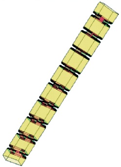
Figure 2. 3D View of 9th order BPF with 10.8 GHz to 11.2 GHz Pass Band using Iris and Cavity Structure
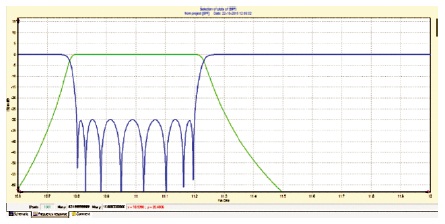
Figure 3. Simulated Response of 8th order BPF Simulation in MICIAN Software with 30 dB Returnloss and 0.04 Insertion Loss in the Pass Band
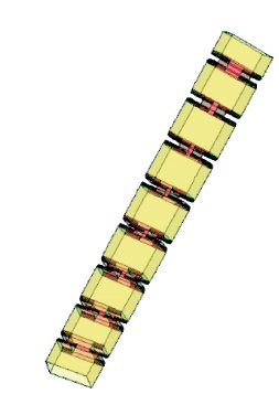
Figure 4. 3D View of 8 Order BPF with 11.4 GHz to 11.7 GHz Pass Band using Iris and Cavity Structure
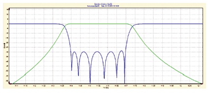
Figure 5. Simulated Response of 9th order BPF Simulation in MICIAN Software with 30 dB Returnloss and 0.04 Insertion Loss in the Pass Band
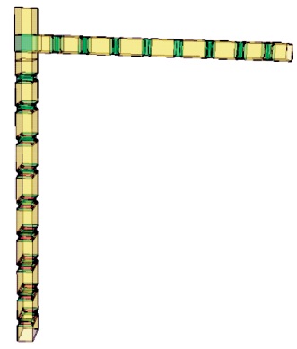
Figure 6. 3D View of Diplexer with Two Designed Band Pass Filters and E-plane T-junction
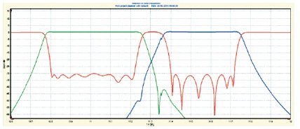
Figure 7. Simulated Response of Diplexer Simulation in MICIAN Software with 30 dB Returnloss and 0.04 Insertion Loss in Both Pass Bands
After meeting the desired specification of the diplexer, it has been fabricated using aluminum material. The inner surface of this filter has been silver plated for better insertion loss. For the better thermal control, the outer surface has been painted using black paints. After fabrication process, the response carried out on PNA (Precision Network Analyzer) meets the desired specification. Simulation of proposed structure is also possible by HFSS tool (Patel & Kosta, 2011; Suvariya & Lavadiya, 2018). Liquid based antenna structure provides better response than copper based antenna for tunability purpose (Kosta & Kosta, 2004; Patel et al., 2020a, 2020b).
High power test consists of power handling test and multipaction test under the vacuum condition. Conventional approach of high power test is complex and costly. According to the research by Kim et al. (2015), measurement using high power test made an effort to achieve traceability to international standard. Few authors used a separate TWTA for an individual channel which shows a complexity of the setup.
Use of diplexer in this setup makes the setup less complex compared to the conventional approach and has been cost effective. Figure 8 shows the block diagram of new approach high power test.
In figure 8, the block diagram shows the new approach in which hybrid has been used for combining the two signals. This combined signal has been amplified using TWTA. At the end, with the help of diplexer, two amplified signal has been obtained separately using the single chain.
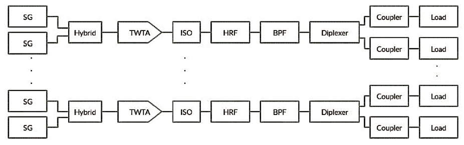
Figure 8. Block Diagram of New Method of High Power Testing
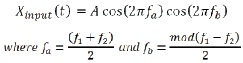
Doshi et al. (2017a), signal generator generates the RF carrier with desired frequencies f and f with amplitude A 1 2 can be represented by,
Combining process of this two carrier has been done by the hybrid device. The output of multi carrier is given by,
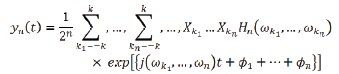
According to the equation, the selected frequency is presented in this combination product. This combination product is known as Intermodulation products. This intermodes affect the original signal carrier. Narrow band pass filter is the solution of this problem. Using the narrow band pass filter, both output ports of the diplexer removes the unwanted carrier.
Tables 1 to 3 shows the comparison of conventional approach and new approach of high power testing. Tables 1 and 2 shows the high power testing measurement using conventional approach while Table 3 shows the high power testing measurement using new approach for the same frequencies. Measurement shows there is no major difference of power level in both approach. Forward power, reflected power and spectrum level in Table 3 are nearly same to the Tables 1 and 2 reading of forward power, reflected power and spectrum level. So, new approach is more convenient because of less setup complexity and low cost.
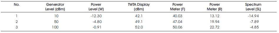
Table 1. High Power Testing at Frequency f = 11.2 GHz using Conventional Approach
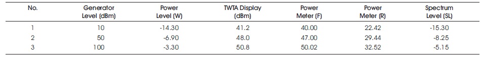
Table 2. High Power Testing at Frequency f = 11.6 GHz using Conventional Approach
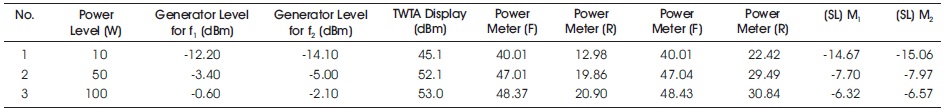
Table 3. High Power Testing at Frequency f1 = 11.2 GHz and f2 = 11.6 GHz using New Approach Technique
This project proposed a new technique for high power testing of spacecraft passive components. Ku-band diplexer is designed in this project using MICIAN μWave wizard simulator with better return loss and insertion loss. Using this diplexer one can separate two amplified signals from using only one TWTAs which results in intermodes with desired frequency signal. With the specific band pass filter this problem can be solved. So any passive components of spacecraft like OMUX, diplexer can be easily tested using this new approach with low cost and less complexity by reducing the travelling wave tube amplifier (TWTA) in the setup using waveguide diplexer.
In future, one can reduce the setup complexity by reducing the number of signal generator used in the setup with the help of multitone signal generator. In this paper normal signal generator used for the experiment generates only one frequency at a time. Use of multitone generator allows to generate more than one frequencies at a time which can be separated using specific diplexer device. Reduction in signal generators and TWTAs results in more compactness of the test setup and also make testing cost effective.
Author would like to thank all the teachers of Marwadi Education Foundation's Group of Institutions, Rajkot, Gujarat, India, and also member of High power test laboratory, Space Application Centre, Indian Space Research Organization, Ahmedabad, Gujarat, India, for their encouragement and support in designing and testing new technique.