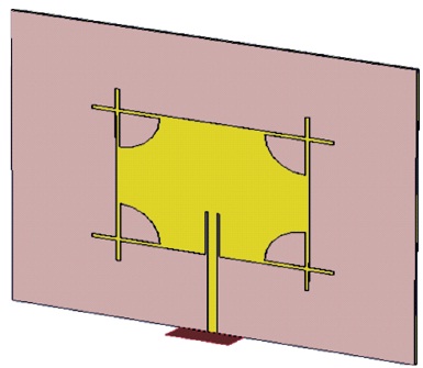
Figure 1. Perspective View of Proposed Antenna
Microstrip patch antennas are used in various applications due to their low-profile structures. The microstrip patch antennas are widely used in commercial, military, industrial, medical and aerospace applications. Normally, microstrip patch antennas are combined with electronic components and integrated circuits. In this paper, microstrip patch antenna is designed using Rogers RT Duroid 5880 as a dielectric substrate, which has low loss tangent with relative 3 permittivity of 2.2, and overall geometric dimensions of 80 x 78 x 0.787 mm . The proposed, microstrip patch antenna is designed and analyzed with CST Microwave studio suite, 2019.The proposed microstrip antenna performs well in simulation, and provides better results. The proposed configuration can be used for ISM band WLAN applications.
Antennas are a primary component of any communications systems. In modern days, Microstrip patch antennas become more popular because of its attractive features, such as low- profile, low cost, less weight, easy fabrication, conformable to planar and nonplanar surfaces and mechanically robust. The concept of microstrip patch antenna was first proposed by Deschamps (1953). After two decades, the first practical microstrip antennas were developed Gutton and Baissinot, (1995), Howell, (1975) and Munson, (1974). During 1980s, technical conferences, journals and symposiums were floaded with microstrip antenna papers as researchers and engineers around the world developed new designs, theories, algorithms, and fabrication procedures.
Nowadays, microstrip antennas are widely used in variety of fields, such as radars, wireless communication, mobile communications, satellite communications, aeronautical applications, the space industry, Global Positioning System (GPS) for detection and identification, and medical applications. These microstrip antennas are used at frequencies ranging from UHF to millimetre waves. The microstrip antenna consists of a radiating patch, ground plane and dielectric material (Kai-Fong,1989; Prakash & Srinivasan, 2014; Sugandh, 2018). The radiating elements and the feed lines are usually printed on the dielectric substrate. The radiating patch may be square, rectangular, thin strip (dipole), circular, elliptical, triangular, or any other configuration. Mostly, square, rectangular, dipole (strip), and circular are common due to its ease of analysis and fabrication, and their excellent radiation field patterns, especially low cross-polarization radiation. These microstrip antennas are excited by different types of transmission fed lines like coaxial, microstrip, or coplanar. The radiating elements are fed directly with electrical continuity between the conductor of the transmission fed line and the conducting radiating patch (Derneryd, 1976; Deschamps, 1953; Gutton & Baissinot, 1955; Howell, 1975; Munson, 1974; Pozar, 1985).
Generally microstrip antennas have numerous advantages, but they have some disadvantages such as narrow bandwidth, poor polarization purity, high quality factor, low gain, low efficiency and spurious feed radiations. The limitations of microstrip antenna are overcame by using different shapes of patches, slotting on the patch, using metamaterials or array structures, and better dielectric substrates (Jothilakshmi et al., 2019; Lee & Chen, 1997; Ray & Kumar, 1999; Waterhouse, 2013;). In this paper, proposed microstrip antenna is designed and simulated, by using CST studio suite. The antenna design consideration and simulated results are discussed and presented. This proposed antenna is well suited for ISM (Industrial, Scientific and Medical) band and WLAN applications.
The proposed microstrip antenna is designed using Rogers RT Duroid 5880 dielectric substrate of 0.787 mm thickness and dielectric constant of 2.2 having loss tangent 0.0009. This proposed microstrip patch antenna contains a metallic radiating patch on top side of a dielectric substrate and has a ground plane on the bottom side. The proposed design is shown in Figure.1.
Figure 1. Perspective View of Proposed Antenna
Figure 1 shows a proposed microstrip antenna with perspective view. The proposed microstrip antenna geometric parameters and inset fed design parameters are calculated based on empirical equations (Balanis, 2016).
Figure 2 shows the optimized geometric dimensions of the proposed structure. The round truncated corner radius as 10mm and narrows strips width as 1 mm respectively. Good impedance matching is achieved between radiating patch and 50Ω microstrip line by optimizing an offset width of feed Wf = 2.38 mm and length of feed Lf = 36 mm. The microstrip patch and ground is made of conducting material such as gold or copper with 0.035 mm thickness.
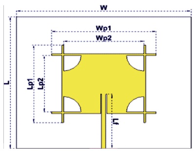
Figure 2. Front View of Proposed Antenna
The microstrip patch and the feedlines are placed on the Rogers RT Duroid 5880 dielectric substrate. The relative dielectric constant of a substrate is usually in the range of 2.2 < εr < 12. Dielectric substrates with lower εr provide better efficiency, larger bandwidth, loosely bound fields for radiation into space. Higher dielectric constant values (εr >10) may be used in special circumstances like for compact antenna designs. The dielectric substrate in microstrip antennas is basically needed for the mechanical support of the antenna.
RT Duroid has attractive features, such as lowest electrical loss for reinforced polytetrafluoro etthylene (PTFE) material, low moisture absorption, isotropic, uniform electrical properties over frequency, and excellent chemical resistance. This dielectric material is well suitable for high frequency applications. The proposed rectangular microstrip antenna is designed and simulated by using CST Microwave Studio and Electromagnetic Software. It is based on the Finite Integration Technique analysis method. The optimized geometric parameters are listed in Table 1.
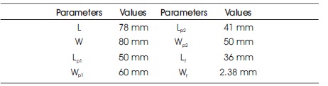
Table 1. Summary of Geometric Parameters
This microstrip antenna is characterized by its length, width, input impedance, gain, and radiation pattern. The length is a very analytical parameter because it controls the resonant frequency of the antenna. Length of the patch is nearly a half wavelength in the dielectric. In these proposed design, microstrip line inset fed is used. The transmission fed line directly connects between the path element and RF source. The benefits of the inset fed method are that it does not requires an additional matching element for impedance matching, simple to design with good impedance matching, and easy for fabrication. Usually, the cost of microstrip antenna depends only on the substrate material and Sub Miniature version A (SMA) connectors. Roger's corporation dielectric materials cost is high, due to its better quality and good radiation characteristics. Good SMA connectors, always provides better impedance matching and better results. Low dielectric loss tangent substrate materials have less dielectric loss, and also very good for antenna applications. Moreover, rectangular design geometries are separable in nature and their analysis is also very simple.
The proposed spiral antenna is designed, simulated, optimized by using CST Studio Suite, 2019 version. CST sIMULATIONS support both high and low frequency applications. This computational software uses the perfect boundary approximation in its transient solutions and it makes finer results with accuracy.
CST includes hexahedral and tetrahedral volume meshes, for time domain solver and frequency domain solvers. In frequency domain solvers, simulation time duration is very high, when compared to time domain solvers. But results are very finer due to tetrahedral meshes. Rogers RT Duroid dielectric substrate provides good stability and reliable features.
Figure 3 shows the return loss plot of proposed spiral antenna design. The proposed antenna has good return loss of 2.4 GHz as -22.35 dB. The return loss is the different between incident power and reflected power of the antenna.
Figure 3. Return Loss Plot for Proposed Antenna
The proposed antenna of the Voltage Standing Wave Ratio (VSWR) is 1.1653 on resonant frequency of 2.4 GHz, as shown in Figure 4. The obtained VSWR value is less than 2. voltage standing wave ratio (VSWR) helps to improve the input impedance characteristics and also displays the impedance mismatch results respectively. VSWR is determined based on the input reflection coefficient.
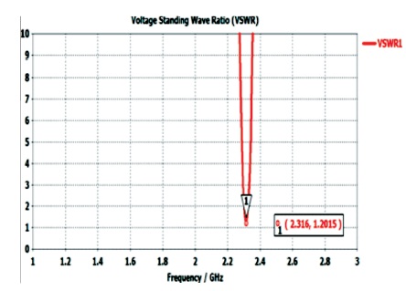
Figure 4. Voltage Standing Wave Ratio (VSWR) Plot of Proposed Antenna
Figure 5 shows the simulated radiation pattern of proposed antenna at 2.4 GHz frequency. Electric field, phi=0 degree represents green dash and phi=90 degree represents red solid line respectively. The radiation pattern or antenna pattern represents the relative strength of the radiated field in various directions from the antenna, at a constant distance. These radiation patterns are used to display the polarization results, as linear, circular or elliptical. Generally, the far-field radiation pattern consists of three dimensions, but practically it is not possible to measure. Two dimensions are slice of the three-dimensional pattern, in the horizontal or vertical planes and it is easy to measure the radiation patterns.
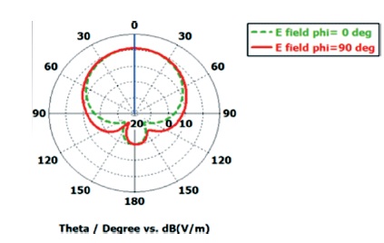
Figure 5. Radiation Patterns in E-field at 2.4 GHz
Figure 6 shows simulated radiation pattern of proposed antenna at 2.4 GHz frequency. Magnetic field, phi=0 degree represents blue dashed line and phi=90 degree represents red solid line respectively. Rogers RT Duroid significantly improves the better radiation field patterns as well as good efficiency. These radiation patterns are presented in a rectangularor polar format. Mostly coordinate polar formats are used in real time process. The polar coordinate system has linear and logarithmic plots, for representing two dimensional radiation patterns.
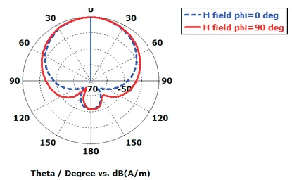
Figure 6. Radiation Patterns in H-field at 2.4 GHz
Figure 6 shows the gain of antenna at 2.4GHz frequency. The gain of microstrip antennas strongly depends on the antenna geometry and the quality of the dielectric materials used. Here, we used RT Duroid 5880 material as dielectric substrate for these proposed design, and it provides better gain characteristics and also increase the antenna radiation efficiency. Rogers dielectric substrate provides best results, in terms of radiation pattern and efficiency. The slot makes good changes in gain characteristics and better antenna radiation efficiency. The proposed antenna yields a gain as 6.29 dB.
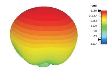
Figure 7. Gain of Antenna at 2.4 GHz Frequency
Figure 8 shows the simulated realized gain, plot of the proposed design. The realized gain normally lesser than antenna gain. The proposed antenna yields a realized gain as 6.26dB. Microstrip array structure and meta surface configurations, to improve the gain and radiation pattern characteristics respectively. The gain of patch antennas depends strongly on the antenna geometry and the quality of the dielectric materials used.
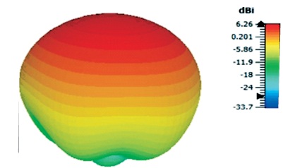
Figure 8. Realized Gain of Antenna at 2.4 GHz Frequency
Figure 9 shows simulated three dimensional directivity plot of the proposed design. Directivity indicates that radiation or reception direction is not constant. When transmitting or receiving signals, directional antennas focus energy only in the specified direction. For mobile applications, omnidirectional antennas are used. In directional antenna, isotropic source was unity since its power was spread equally in all directions. Moreover, directional antenna has narrow beam width than sectoral antennas. This proposed antenna has good directivity result as 8.17 dBi, in single patch element.
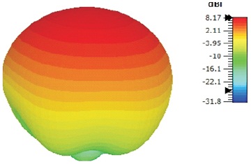
Figure 9. Directivity of Antenna at 2.4 GHz Frequency
Figure 10 shows simulated input impedance plot of the proposed structure. The normal impedance matching is 50 ohms. This proposed antenna achieves good impedance matching with respect to antenna fed. The input impedance of an antenna is a function of frequency. Antenna impedance always relates the voltage to the current at input terminal. Input impedance has real and imaginary parts; real part represents the resistive part and imaginary part represents the reactive parts. The input impedance is extremely important parameter, to improve the antenna performances.
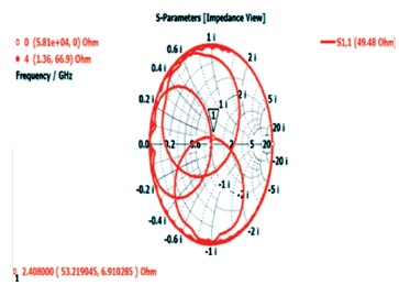
Figure 10. Simulated Impedance of Antenna
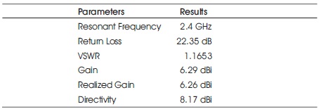
Table 2. Summary of Results
A novel microstrip antenna is designed and simulated by electromagnetic computational software as CST Studio suite. This proposed structure operates in 2.4 GHz resonant frequency. The proposed antenna is well suited for ISM (Industrial, Scientific and Medical) band and WLAN applications. The use of Rogers RT Duroid 5880 substrate, significantly improves the performance of antenna in terms of gain, directivity, return loss, vswr, and radiation efficiency respectively. Fabrication, testings and measurements for proposed design will be conducted as future work.