Figure 1. Implementation Block Diagram
Using light to exchange RF signal has been rapidly developed since the innovation of optical fiber and semiconductor laser in 1960s. A Photonics Antenna (PA), which brings together the world of radio frequency engineering (radiation of EM wave) and optoelectronics devices (laser, photo diode), has attracted and was given great importance from both the research group of people and the commercial sector over the past 30 years and is set to have a bright future. The essential focal point of photonics for antenna system has truly been on the advancement of connection and beam steering techniques. By utilizing photonically controlled gadgets and materials, it is conceivable to deliver progressive changes in receiving antenna components and in the structure and properties of exhibits, opening the new door for another class of Antenna. This technology enables complex or even impossible functions in the field of Radio Frequency (RF) in microwave systems and creates new opportunities for telecommunications networks. The authors present the technology of the photonics community and summarize current research and important applications. This review paper summarizes the comprehensive study of photonics feeding antenna, or Photonics for antenna characteristics, possible applications and wireless communication challenges of this promising type of Antenna.
In today's rapidly changing wireless technologies, and with accelerating advances in technology, Statement from Wireless World Research Forum (WWRF); which has motivated our efforts to give superior mobile communications for people; 7 trillion wireless devices have served 7 billion Citizens in 2017 (David, 2008). This essentially means that the entire world Population will be served by wirelessly communicating devices. Therefore it is necessary that the desired communication system should be in a miniaturization structure and it is also required for achieving an optimal design and effective bandwidth, this will be achieved by photonics handheld wireless communication system (Lee, 2013). So there are new demands for wireless communication system that integrated components including antennas. Numerous techniques have been projected by researchers for the miniaturization of photonics based microstrip patch antennas with multiband characteristics (Nanyan, Hashim, Ngah, Rahayu, & Prakoso, 2010a). Antenna and Microwave is the heart of the communication industry. The development and investigation in photonics based antenna have provided be a good strategy in order to obtain a dynamic changes in the wireless industry, which has enabled the wide bandwidth, high efficiency, high speed, and dramatic reduction in size and weight, high speed data transmission behavior (Lee, 2013; Nanyan, Hashim, Ngah, Rahayu, & Prakoso, 2010).
Photonic devices and subsystems have been imagined as a future possibility as enabling technologies for the radiation, transmission, detection, processing, and control of microwave photonics signals in Radio Frequency (RF) systems for many decades. The inherent advantages of microwave photonics (Nanyan et al., 2010; Yao, 2009a), including wide input bandwidths, lowtransmission loss over long distance and electromagnetic interference free signal transport, lightweight, small size and flexible cabling, and signal multiplexing allowing reduced cabling. Yao (2009b) have driven the growth and prosperity of this field. Despite the many successes demonstrated over the years, widespread use of photonic subsystems has been confined by a number of initial limitations. The most notable limitation has been the inefficiency of the conversion from the microwave to optical domain and back, as well as added noise and distortion. These factors have been key impediments to reaching the full potential of photonics. Recent developments have demonstrated great promise.
Photonics feeding antennas are an emerging concept in physical optics. Similar to radio-wave and microwave antennas, their purpose is to convert the energy of free propagating radiation to localized energy, and vice versa.
Sittakul and Cryan (2007) describe a low-cost plan to implement in-building distributed antenna systems using photonic-active-integrated-antenna (PhAIA) concept, under which photonic devices are integrated directly with Planner antennas is done. Deformed input impedance is measured for 850-nm vertical-cavity surface-emitting laser and photodiode from 0-10 GHz, and the devices are directly matched to the non-radiated edge of a rectangular-microstrip-patch antenna. Link Gain, 1-dB Compression Point, and Spurius-Free Dynamic Range Link Fully bidirectional system, which is far from fully customized, then the laboratory-based multimode fiber link of 300 meters and the 220-meter building dark-fiber link is tested. Results are shown for throughput and signalto- noise ratio, and this paper shows that such systems can get without RF amplification, up to 10-M RF limit on low throughput (Sittakul & Cryan, 2007).
Suresh and Sundaravadivelu (2007) have proposed a structure for photonic antennas after analyzing its capacity and suitability for wireless optical communication using the conventional transmission line analogy. But they have used a novel idea that is analyzing the non-linear filtering effects of triangular grating structure with metal strips (non-linear structure) and then designing the photonic antenna (Suresh &Sundaravadivelu, 2007).
Jianping Yao proposed UWB impulse technology that has been around for a few decades and has applied it mainly to radar systems. Its application to broadband wireless communications has only recently been explored (Yao, 2009).
Teguh Prakoso and his co-authors have proposed an Active Photonics Antenna for wireless communication system at 2.4 GHz. APhA includes a photodiode, an RF amplifier, and a bandpass filter (BPF) in a small box, integrated into an RF antenna. APhA design is simulated using optical communication simulation software at varied fiber length and free space loss (Prakoso, Ngah, & Rahman, 2008).
In another research, the above said researchers present the design and simulation of a photonic antenna for a long-range application. The antenna is designed for a frequency of 5.8 GHz because the operating frequency is commonly used for terrestrial and long-distance WLAN networks (Prakoso, Ngah, Rahman, & Mualif, 2008).
Yashchyshyn and his co-authors have investigated a successful demonstration of the use of the active photonic integrated antenna in the wireless system, when microwave communication signals are transmitted between the access points and the antenna points in the antenna distribution systems via an optical fiber. The results of the comparative study of the degradation of the dynamic range of the different system configurations caused by the insertion of the fiber optic link and the active integrated photonic antenna were presented (Yashchyshyn et al., 2007).
In 2010, Nanyan et al. proposed a new wideband photonic antenna consisting the laser diode, matching circuit, RF amplifier, and micro strip patch antenna, which are fabricated and connected together to perform in uplink system. The results show useful photonic antenna design that achieves reasonably wide bandwidth and has potential to be applied in RoF technology (Nanyan, Hashim, Ngah, Rahayu, & Prakoso, 2010).
Further, Mohammad Faizal Ismail proposed the design and development of wideband antenna using logperiodic technique. The integration of the antenna with PIN diode switches and lumped elements forms the reconfigurable antenna that enables the antenna to select several sub-bands from a wideband frequency (Ismail, 2011).
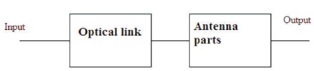
After literature review, these are found that the microwave antennas are feeded by microstrip line or coaxial line with the help of microwave connector. The microwave power is transmitted to and from the antenna by means of RF cable. In the photonic antenna, the basic building block diagram is as shown in Figure 1, whose initial parts are optical link or photonic link that are integrated with Antenna part. This means that the RF cable is replaced by an optical link or microwave photonics link, therefore it is required to use optoelectronic components, such as lasers and photodiodes for the transformation of microwave signal to modulated the optical signal and vice-versa (Ismail, 2011). The integration of Photonic Component (PC) with any kind of antenna such as patch antenna is called Photonics Antenna or the photonically feeding to patch antenna comes under the photonics Antenna.
Figure 1. Implementation Block Diagram
Photonic monolithic antennas have the following advantages:
Photonics is the field that includes the utilization of brilliant vitality, (for example, light), whose major component is the photon. Photonic applications utilize the photon similarly that electronic applications utilize the electron. Devices that keep running on light have various points of interest over those that utilize power. Light goes at around multiple times the speed that electric power does, which implies (in addition to other things) that information transmitted photonically can travel long separations in a small amount of the time. Besides, visible-light and infrared (IR) beam, in contrast to electric flows, go through one another without communicating, so they do not cause obstruction.
A single optical fiber has the capacity to carry three million telephone calls simultaneously (Fakoukakis, Kaifas, & Kyriacou, 2012; Sittakul, & Cryan, 2007). Photonics for antenna application, it means, this unites radio frequency engineering with optoelectronics devices (VCSEL and photodiode) (Nanyan et al., 2010; Tzeremes, Tanner, Liao, & Christodoulou, 2004). It creates a variety of significant functionalities that are either too complex or even impossible to achieve in the radio frequency domain and can offer the enhanced performance or support new applications for broadband communications, imaging, and instrumentation. Here the authors highlight the on-going research in the field of Photonics based Antenna. The distribution of RF signal via optical or photonically further comes under radio over fiber technology (ROF).
With the growing demand of bandwidth and mobility in wireless communication system and rapidly increasing mobile phone users, a new concept or technology is introduced, which sorts out the problems of increasing demand for broadband services. The future generation of cellular network will need much lesser network size than the present used networks. To overcome this problem, Radio over fiber (RoF) and Photonics antenna are introduced for these applications (Marti & Capmany, 2009).
Radio over Fiber (RoF) Technology refers to an analog transmission over optical fiber, whereby light is amplitude modulated by a radio signal and transmitted over an optical fiber link to facilitate wireless access.
In wireless-photonics systems, two popular communication approaches are available (Marti & Capmany, 2009; Chuang et al., 2008): Radio-over-Fiber (RoF) and digital baseband optical communication (Figure 2). It should be noted that in this classification, RoF includes both Radio- Frequency (RF) and Intermediate-Frequency (IF) over fiber. The overall structures of typical links using these two approaches are shown in Figure 3. As it can be seen from the figure, the digital baseband approach does not require the RF up- and down-converters and thus its design is typically simpler. It should be noted that the modulation scheme commonly used in the digital baseband approach is On–Off Keying (OOK) which is significantly simpler as compared to the one used in RoF. In RoF, often, Quadrature Amplitude Modulation (QAM) or Orthogonal Frequency Division Multiplexing (OFDM) are used (Yashchyshyn, Chizh, Malyshev, & Modelski, 2010). Although RoF uses more complex modulation schemes, it typically requires a lower bandwidth for the same data rate; it is likely for the most straightforward radio signal distribution scheme because the wireless signals are transported directly over the fibre at the radio.
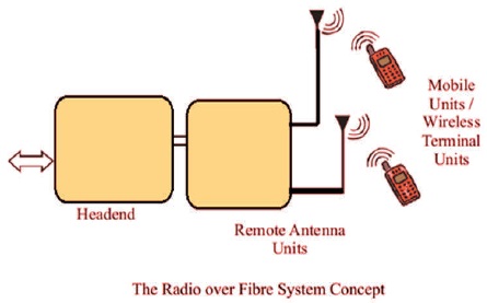
Figure 2. Radio over Fiber Communication System
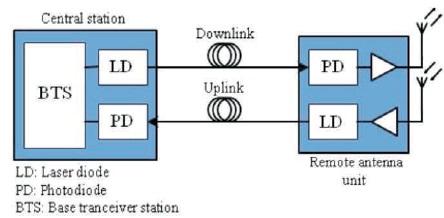
Figure 3. Implementation Block Diagram of RoF
In RoF systems, wireless signals are moved in optical form between a central station and a set of base stations before being transmitted through the air. Each base station is adapted to communicate over a radio link with at least one user's mobile station located within the radio range of the said base station. RoF transmission system are normally grouped into two fundamental classes (RF-over- Fiber; IF-over-Fiber) (Jia, 2008), depending upon the frequency range of the radio signal to be moved in RF-over- Fiber design, an information conveying RF (Radio Frequency) signal with a high frequency (generally more prominent than 10 GHz) is forced on a light wave signal before being shipped over the optical connection. In this manner, remote signal are optically conveyed to base stations straightforwardly at high frequencies and changed over from the optical to electrical space at the base stations before being amplified and transmitted by antenna. Therefore, no frequency up/down change is required at the different base stations, consequently bringing about basic and rather cost effective execution is empowered at the base stations (Porcino & Hirt, 2003). In IF-over-Fiber model, lower frequency (less than 10 GHz) radio signal is used for modulating light before being carried over the optical link. Therefore, before radiation through the air, the signal must be up-converted to RF at the base station. An RF signal can be transmitted, up to many GHz depending on the laser and its modulation scheme. The RF Out must be amplified to provide a useable signal. Radio-over-Fiber (RoF) technology entails the use of optical fiber links to distribute RF signals from a central location (headend) to Remote Antenna Units (RAUs) as shown in Figure 2 (Cox, 2006).
The RF signal processing function, for example, frequency up-transformation, carrier modulation, and multiplexing, are performed at the BS or the RAP for narrowband correspondence systems and WLANs, and quickly fed into the antenna. In the common area (headend), RoF makes it conceivable to unify the RF signal handling capacities in a single end and after that to utilize optical fiber, which offers low signal loss (0.3 dB/km for 1550 nm, and 0.5 dB/km for 1310 nm wavelengths) to appropriate the RF signal to the RAUs (Aiello & Rogerson, 2003).
There are many benefits of radio over fiber technology based electromagnetic sensor (Yang & Giannakis, 2004) (Photonics Antenna) compared to other conventional electronics signal or radio frequency distribution. They are low attenuation, low complexity, lower cost, etc.
Fiber Optics are intended to deal with gigabits speeds, which means they will most likely deal with paces offered by future generations of networks for the years to come (Yao, 2009b). RoF innovation is likewise protocol and bit-rate straightforward, henceforth can be utilized to present and future advancements.
Converting RF signals into an optical output for transmission through a fiber-optic cable avoids the bandwidth and loss limitations of coaxial cables or waveguides and reduces weight and volume. By transferring RF signals to the optical domain, Microwave Photonics has enabled traditional Electronic Warfare applications such as antenna remoting to become more flexible while reducing bulky and lossy metallic links (Yao, Zeng, & Wang, 2007). Microwave Photonics is very attractive for antenna remoting applications not only because of the bandwidth advantages of using fiber optics transmission, but also because many signal processing functions, that are difficult in the RF domain, can be implemented with relative ease in the optical domain while maintaining broadband operation. One such example is broadband splitting or summation of RF signals. Before embarking onto Microwave Photonic combination systems, it will be necessary to review Microwave Photonic links or RoF Link. In general, the Radio over Fiber technology covers the following process to access the optical signal.
The RF Photonics signal is used to directly modulate the laser diode in the central site (headend). The resulting amplitude modulated optical signal is then transported over the length of the fiber to the BS (RAU). At the RAU, the transmitted RF signal is recovered by direct detection in the PIN photodetector. The signal is then amplified and radiated by the antenna. The uplink signal from the MU is transported from the RAU to the headend in the same way. The objective of optical design is to generate modulated RF signal with optical carrier (laser) and the result from both signals will be modulated and fed to an optical fiber as a transmission line (Chang, 2007; Nassar, Zhu, & Wu, 2003). This method of transporting RF signals over the fiber is called Intensity Modulation with Direct Detection (IM-DD), and is the simplest form of the RoF link (Balakrishnan, Batra, & Dabak, 2003).
Figure 4 shows the circuit of photonics antenna.
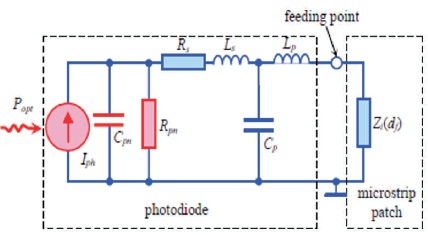
Figure 4. Equivalent Circuit of Photonics Antenna
Iph : current generated by incident light (proportional to light level)
VD : voltage across diode
ID : diode current
CJn : junction capacitance
Rpn : shunt resistance
I': shunt resistance current
Rs : series resistance
Vo : output voltage
Io : output current
impedance Zi.
The photodiode is represented by current source Iph, p-n junction capacitance Cph (0.07 pF).
This part introduces fundamental Microwave Photonic link configurations for antenna remoting systems. It explains how the signals received from the antennas can be combined using photonic multiplexing techniques into a single optic-fibre system. Figure 5 shows the basic configuration used to characterize a photonically remote antenna system using a Microwave Photonic link (Ishida & Araki, 2004; Cox, 2006). A continuous wave laser diode (LD) is connected to an electro-optic intensity modulator for external modulation. The RF signal applied to the electrodes of the modulator, modulates the intensity of optical carrier, converting the RF signal into the optical domain. This electro-optic modulated signal is transmitted through optical-fibre links and is converted back into the electrical domain using a high sensitivity Photo Detector (PD) (Lin & Chen, 2005).
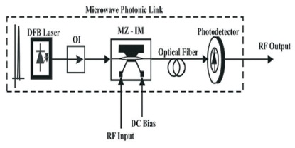
Figure 5. Microwave Photonics Link Configuration
Polarization Maintaining (PM) optical fibers and coaxial cables are employed to interconnect the components and conversion stages of the Microwave Photonic link. The PM fibers ensure that the polarization of the optical carrier complies with the polarization requirements of the electro-optic modulator. Mach-Zehnder modulators (MZMs) have a sinusoidal response that can be biased at different points of its transfer function in order to generate different modulation results (Wang & Yao, 2007). One possibility is to bias at a null, where the carrier is suppressed and the modulation occurs in the second harmonic (Wang & Yao, 2008). However, MZMs are normally biased at quadrature, where they are more linear, in order to provide maximum gain and minimal harmonic distortion (Dai & Yao, 2008; Lim, Nirmalathas, Lee, Novak, & Waterhouse, 2007; Lim et al., 2009). The link gain of a Microwave Photonic link is defined as the ratio of the detected RF output power at the photo detector to the input RF power (O'Connor, Clark, & Novak, 2008). For a Microwave Photonic link using a MZM and without amplification, the link gain is given by,
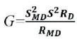
where SMD is the slope efficiency of the modulator, SD is the slope efficiency of the photo detector (also known as responsivity), RD is the load impedance of the photo detector and RMD is the modulator impedance. The slope frequency of the modulator can also be defined by,

where tff is the fibre to fibre optical transmission losses of the modulator plus any interconnection loss along the optical link, Pl is the CW input optical power of the modulator, RIN is the impedance of the RF modulating source, and Vπ is the switching voltage of the modulator (Cox, Ackerman, Betts, & Prince, 2006). By replacing equation (2) into equation (1) and assuming that the impedance of the modulator is matched to the impedance of the RF source (RIN = RMD), equation (1) can be expressed as,
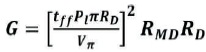
The parameters of the microwave photonic link equipment used in this investigation, listed in Table 1, can be used in equation (3) to approximate the total RF attenuation of Microwave Photonic links without amplification.
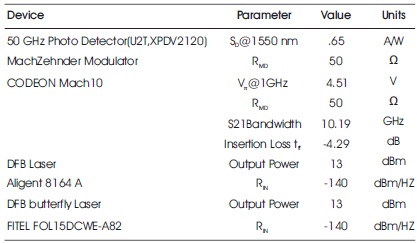
Table 1. General Parameters
This attenuation is about -40 dB, which it could be considered to be a disadvantage for photonically remote antennas. However, this attenuation can be compensated due to the fact that a photonic system exhibits a Noise Power levels lower than the RF system.
For the performance of RF/Photonics systems for wireless communications, there are three main steps to follow for design a Photonics Antenna (Cox et al., 2006). The first stage is to use optoelectronics components such as photodetector to replace with conventional RF components, such as the coax, which is interconnected with Electromagnetic sensor, i.e. Antenna to the electronics since optical fiber, advantages, increased immunity to EMI, and the ability to increase the distance between the antenna and the electronics provide a better medium for broadband RF communication systems. The thread like structure and lightweight property of fibers, low loss, and its immunity to other signal interference make them ideal in the development of future RF distribution systems (Way, 1987). The second stage is incorporation of photonic components and RF wireless circuits in the form of Optoelectronic Integrated Circuits (OEICs). Practically, insertions of commercial RF systems come under Fiber-optic technologies, in this stage. In the third stage, the endeavor is to reduce cost by eliminating the need of local oscillators, mixers, amplifiers, and a host of other parts by directly feeding an antenna through a fiber.
The third step is called passive integrated antenna or simply photonic antenna. The presence of connector at optoelectronics interface to receiving wire present losses. Evacuating the connector, the issues can be survived and some different increments in execution can be acquired as well, for example, duplexing, filtering, beam forming, impedance matching, increasingly smaller, and lightweight (Chen, Ram, & Helkey, 1999). The notion began with integration of waveguide photo detector to microstrip antenna via coplanar waveguide.
Figure 6 shows the Microwave Photonics link configuration for antenna remoting. This antenna consists of two independent parts: fiber-optic photodiode module and conventional microwave antenna, which are connected together by means of microwave connectors. In the monolithic photonic antenna, the photodiode is integrated with microwave antenna, and the photocurrent generated by photodiode directly excites the antenna (Novak & Waterhouse, 2013). One of the problems of working with Photonics feeding Antenna is that the efficiency of the transmitting photonic antenna can be increased by means of the optimal matching of the photodiode with the radiator, with no matching networks and no RF amplification. The efficiency of the receiving photonic antenna can be additionally increased by means of the optimal matching of the laser diode with the radiator, with no RF amplification.
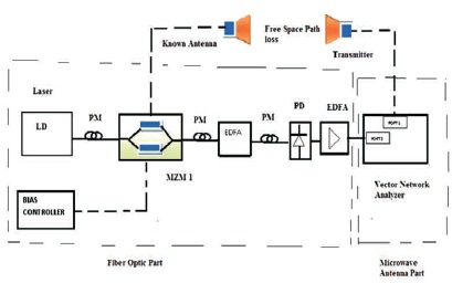
Figure 6. Microwave Photonic Link Configuration for Antenna Remoting
The most notable limitation has been the inefficiency of the conversion from the microwave to optical domain and back, as well as added noise and distortion. These factors have been key impediments to reaching the full potential of photonics.
Photonic antenna can be implemented as a new hardware design base on the simulation had been done in this research work. The results from this work will give a very good reference for future study on photonic antenna. This is a new technology that will make the wireless communication world become more challenging and interesting. The results of the comparison of the conventional fiber-optic link and the photonic antenna have been illustrated as well. It is shown that the efficiency of the receiving photonic antenna depends on the relative intensity noise of the laser diode and that the efficiency of the transmitting photonic antenna can be increased by means of the optimal matching of the photodiode with the radiator, with no matching networks and no RF amplification. The efficiency of the receiving photonic antenna can be additionally increased by means of the optimal matching of the laser diode with the radiator, with no RF amplification.
This work is supported by Space Applications Centre, Indian Space Research Organization (ISRO), Ahmedabad, India with ISRO Respond project entitled “A novel Mach-Zehnder Modulator based integrated photonic highly steerable beam-forming system for broadband satellite communication link”. The work is carried out under Project number: ISRO/(10)/2018- 2019/571/ECE (Grant No. DS-2B-13012(2)/13/2018). Authors also would like to thank the SAC-ISRO Ahmedabad for providing the necessary experimental facilities.