
Figure 1. Basic Circular Patch Antenna
Conformal antennas are required whenever an antenna has to conform geometrically to some shaped surface. In this paper, a cylindrical conformal antenna array with line feed technique is implemented. At first, an inverted U- slotted non conformal circular patched antenna with a radius of 16.3 mm, thickness of 1.6 mm, and a substrate permittivity of 4.4 is designed to operate at 2.4 GHz. The simulated results are in close agreement with the measured results. The measured S11 for non-conformal antenna is -17.4 dB at 2.4 GHz. The inverted U-slotted circular patch antenna is made conformal to cylindrically bent substrate of thickness 0.762 mm with a permittivity of 2.55 and it resonates at 2.63 GHz. Further, an array of three elements of conformal U-slotted circular patch antenna flush mounted on cylinder 1200 apart. From the results, it is evident that gain is increased with cylindrical conformal array antenna. The gain of proposed conformal array antenna is of 5.02 dB. Simulation is carried out using HFSS software.
Conformal antennas are developed in the 1980's. In radio communication and avionics, conformal antennas or conformal array is a flat radio antenna, which is designed to conform or follow some prescribed shape. Important feature of these antennas is their radiation characteristics. Antennas on a single curved surface are the simplest case of the conformal antennas. The main purpose of developing conformal antenna structures is to obtain omni-directional azimuthal coverage. Conformal antennas are used especially in airplanes and other airborne vehicles at microwave frequencies and in Wireless Local Area Networks (WLAN) at mm-wave frequencies to achieve high speed connections (Chreix, 1936; Josefsson, & Persson, 2006). Different types of slots are incorporated to improve the gain of the patch antennas (Muvvala, Reddy, & Darimireddy, 2017). The shape of the antenna is conformal to the surface of a cylinder such that the antenna can be completely integrated within the body of a cylindrical carrier without protruding components. The design and performance of a conformal dual band patch antenna operating in the Lband frequency is reported in (Yinusa, 2018). The prototype of the antenna in its planar and conformal versions exhibits the wideband characteristics (Madhav, Anilkumar, & Kotamraju, 2018). Conformal patch antenna arrays are usually excited through several probe feeds and coaxial lines, which are costly and less reliable in millimeter-wave applications (Jaeck et al., 2017; Sanchez-Dancausa, Masa-Campos, Sanchez-Olivares, & Marin, 2016). For conformal array antennas, the printed circuits must be bent to integrate it into a specific curved surface. The bending of the dielectric substrate can produce a considerable efficiency reduction of the antenna, especially for large microstrip arrays (Semkin et al., 2013, 2015). A circularly conformal array antenna of double stacked microstrip patches is presented in two radiation versions as omnidirectional and electronically switched directive beam (Sanchez-Olivares, Sanchez- Dancausa, & Masa-Campos, 2017).
In this paper a conformal antenna using line feed technique that, operate at a frequency of 2.45 GHz is proposed. An array of three circular patch antennas separated with 1200 is presented.
The basic circular patch antenna with a radius of 16.3 mm operating at 2.45 GHz is shown in Figure 1. A quarter wave transformer is used for impedance matching purpose.
Figure 1. Basic Circular Patch Antenna
For the circular patch antenna given, a return loss of -16.9 dB is obtained at 2.55 GHz frequency as shown in Figure 2. The peak gain of basic circular patch antenna is 2 dB operating at 2.55 GHz and the corresponding radiation pattern is shown in Figure 3. Surface current distribution of circular patch antenna is shown in Figure 4.

Figure 2. Return Loss for Circular Patch Antenna
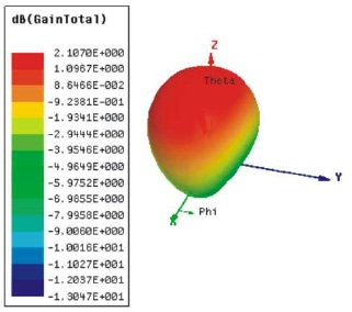
Figure 3. (a) 3D Gain, (b) Radiation Pattern for Circular Patch Antenna
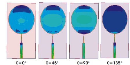
Figure 4. Surface Current Distribution of Circular Patch Antenna
The circular patch antenna with inverted U-slot is shown in Figure 5. The return loss for circular patch antenna with inverted U-slot is -17.4 dB operated at 2.4 GHz, which is shown in Figure 6. The peak gain is 2.1 dB and radiation pattern is shown in Figure 7. Surface current distribution of circular patch antenna with inverted U-slot is shown in Figure 8.
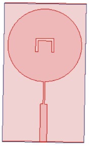
Figure 5. Circular Patch Antenna with Inverted U-slot
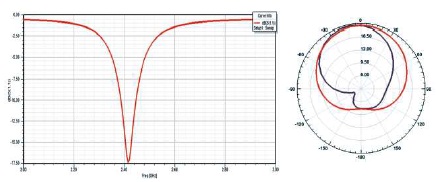
Figure 6. Return Loss for Circular Patch Antenna with Inverted U-slot
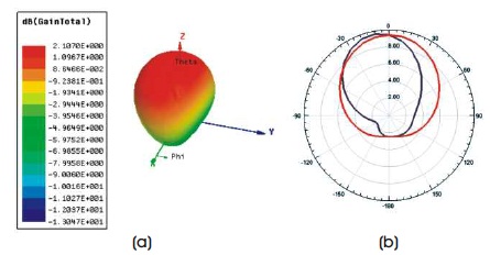
Figure 7. (a) 3D Gain, (b) Radiation Pattern for Circular Patch Antenna with Inverted U-slot

Figure 8. Surface Current Distribution of Circular Patch Antenna with Inverted U-slot
Fabricated circular patch antenna with inverted U-slot and experimental setup are shown in Figures 9 and 10, respectively. Practical measurements are done by using vector network analyzer (E5071C). The return loss of the circular patch antenna with inverted U-slot is less than –21.5 dB at 2.28 GHz and is shown in Figure 11.

Figure 9. Fabricated Structure of Circular Patch Antenna with Inverted U-slot
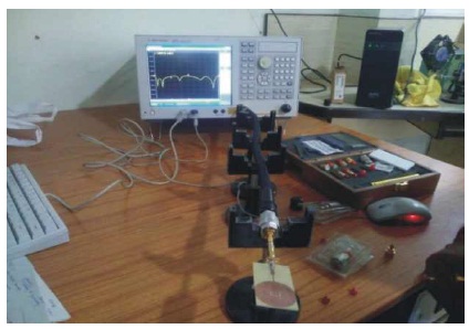
Figure 10. Experimental Setup for Practical Measurement
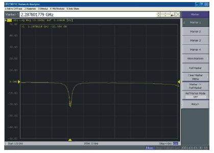
Figure 11. Return Loss of Fabricated Circular Patch Antenna
The cylindrical conformal antenna with thickness 0.762 mm, radius 38.762 mm, and height 62 mm is designed to operate at 2.45 GHz and is shown in Figure 12. The advantage of using the conformal antenna is that it can absorb information from any angle.
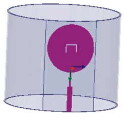
Figure 12. Cylindrical Conformal Antenna
The return loss for cylindrical conformal antenna is -15 dB at 2.63 GHz is shown in Figure 13. The peak gain is 4.47 dB and radiation pattern is shown in Figure 14.
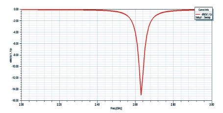
Figure 13. Return loss for Cylindrical Conformal Antenna
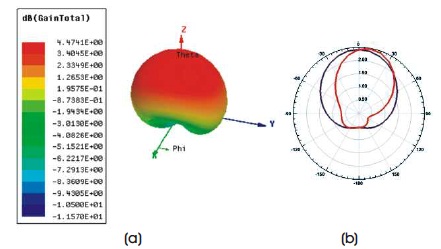
Figure 14. (a) 3D Gain, (b) Radiation Pattern for Cylindrical Conformal Antenna
Surface current distribution of cylindrical conformal antenna is shown in Figure 15.

Figure 15. Surface Current Distribution of Cylindrical Conformal Antenna
Cylindrical conformal antenna array with three circular patches are placed at 1200 each is presented in Figure 16.
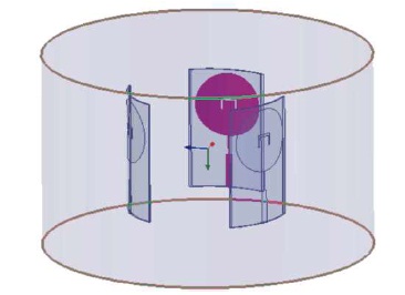
Figure 16. Cylindrical Conformal Antenna Array
The proposed conformal array is parametrized for different cylinder radius (36 mm to 38 mm) as shown in Figure 17. It is evident from the results, the resonant frequency shifted from 2.59 GHz to 2.63 GHz, where the S11 is also improved from -14 dB to -16 dB as the cylinder radius is increased from 36 to 38 mm. The return loss of cylindrical conformal antenna array is -15.7 dB at 2.63 GHz and is shown in Figure 18. The gain obtained is 5.02 dB. Further, modifications are under study, in order to obtain the desired resonance of 2.45 GHz and CP radiation. The radiation Pattern is shown in Figure 19.

Figure 17. Parametric Study for Different Cylinder Radius (R=36 mm, R= 37 mm and R= 38 mm)
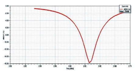
Figure 18. Return Loss for Cylindrical Conformal Antenna Array

Figure 19. Radiation Pattern for Cylindrical Conformal Antenna Array
Comparison of simulated results of circular patch, circular patch with slot, cylindrical conformal, and cylindrical conformal array antenna are shown in Table 1. From the results it is evident that using conformal structure with single element and array with 3 elements, return loss is reduced and gain is increased.
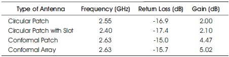
Table 1. Comparison of Circular Patch Antenna with Conformal Antenna Array
The circular patch antenna is designed to operate at a frequency of 2.45 GHz, with return loss -16.9 dB and gain of 2 dB. The circular patch antenna with inverted U-slot return loss is -17.4 dB and gain 2.1 dB. The simulated results are compared with practical results. The cylindrical conformal antenna is designed to operate at same frequency, return loss -15 dB, and gain 4.47 dB. Cylindrical conformal antenna array is designed with 3 circular patches placed at 1200 each resulting in small deviation in the operating frequency with a return loss of -15.7 dB at 2.63 GHz and gain of 5.02 dB. From the results it is evident that by using Cylindrical conformal antenna array, the gain can be increased.