Figure 1. Procedure for Applying the Elliptical Slots in Conventional Circular Patch
In this paper, elliptical slots loaded circular patch antenna for wireless communications has been investigated. The proposed antenna is modified by varying the length of ground plane to increase the impedance bandwidth over the frequency range of 1 - 10 GHz. Simulated results of proposed antenna exhibits the bandwidth of 3.34 GHz (1.46 - 4.80 GHz) and 3.01 GHz (5.05 - 8.06 GHz). The proposed antenna can be used in various wireless applications, covering the Global System for Mobile (GSM) standards (DCS 1.71 - 1.88 GHz and PCS 1.85 - 1.99 GHz), UMTS (1.92 - 2.17 GHz), Bluetooth (2.41 - 2.49 GHz) of ISM band, 2.45 GHz WLAN of IEEE 802.11 b/g/n, 5.15 GHz WLAN of IEEE 802.11 a/n, WiMAX (2.5 - 2.69 GHz, 3.4 - 3.69 GHz, and 5.25 - 5.85 GHz), X-band for satellite communication (7.25 - 8.39 GHz) and point to point high speed wireless application (5.925 - 8.5 GHz) bands. Antenna is designed and fabricated on FR4 glass epoxy substrate to validate the simulated results with the measured results. Comparisons of both the results are found to be in agreement with each other. It also shows the good omnidirectional radiation pattern, appreciable gain, and acceptable radiation efficiency over the entire frequency range of 1 - 10 GHz.
In recent years, with the development in the field of wireless communication, the need of low cost, low profile, multiband and wideband antennas are increased (Lee & Sun, 2009; Bakariya et al., 2015a). Microstrip antennas become the most popular and are widely used in the modern communication systems because of their tremendous advantages like low cost, low profile, lightweight, ease of fabrication, and portability (Khandelwal et al., 2015; Khan et al., 2015; Sivia et al., 2017). Though, the microstrip antennas have many disadvantages such as narrow bandwidth which limits the use of microstrip antennas in wideband applications (Bakariya & Dwari, 2012). Modern communication system requires the system which supports the more number of applications at different frequency bands with wide bandwidth (Reddy and Sarma, 2014). Due to the requirement of high data rate and wide bandwidth in the modern communication system, Federal Communications Commission (FCC) allocates the Ultra-wide frequency band (3.1-10.6 GHz) for commercial uses (Karmakar et al., 2013). Being a very much essential part of the modern communication system, wideband antennas are gaining momentum. Due to which, these antennas have good omnidirectional radiation pattern and stable gain (Sarkar et al., 2013). The Ultra-wideband (UWB) antennas have many advantages, such as low power consumption, high data rate capability, less interference, easy installation, etc. (Bhatia & Sivia, 2016). Many narrow band interference exists in the UWB systems, such as WLAN (5.15- 5.825 GHz) IEEE 802.11a, Fixed Broad Wide Band Access 3.5 GHz (Zhang et al., 2008), and X-band downlink at 7.5 GHz. These interferences are avoided by the use of band stop filter, but it increases the cost and complexity of the system (Bakariya et al., 2015a; Li et al., 2010). Recently, several antennas with different configurations, such as hexagonal, circular, triangular, and monopolar are designed for wideband applications (Fallahi & Atlasbaf, 2015; Liang et al., 2005; Liu et al., 2013; Faruque et al., 2015; Deshmukh & Ray, 2015). A number of researches has been done to achieve the stable gain and wider bandwidth. In these researches, different techniques are applied by the researchers, such as employing the defects in the ground plane, designing the partial ground plane, using the slots in the patch or ground plane, varying the size of antenna, or by adding the multilayers in the antenna (Bakariya & Dwari, 2012; Gopikrishna et al., 2009).
Different types of antenna has been designed by the researchers by using the slotted patch to achieve the wideband characteristic; microstrip antenna with multiple circular slots with the bandwidth of 95 MHz at 2.5 GHz (Farooq et al., 2015); pentagon slot antenna for wideband reconfiguration with bandwidth of few MHz (Borakhade & Pokle, 2015); U- shaped slot loaded rectangular microstrip antenna is designed for broadband operation to achieve the bandwidth of 80.4% ranging from 2.58-6.05 GHz (Verma & Ansari, 2015) and Commercial Processing Workload (CPW) fed hexagonal microstrip fractal antenna is designed for UWB wireless applications (Sawant & Kumar, 2015). However, many antennas are also designed by using defected ground plane to achieve the wideband characteristics; fractal based UWB monopole antenna is designed to achieve the bandwidth of 120% ranging from 2.7-10.9 GHz (Karmakar, 2013); compact printed monopole antenna is designed for UWB applications to achieve the band notch at two bands such as 3.4-3.6 GHz and 5.6-5.8 GHz (Sarkar et al., 2013); triple band notch monopole antenna is designed for UWB applications (Bakariya et al., 2015b); bandwidth enhancement of CPW fed monopole antenna is designed to achieve the UWB characteristics using small fractal elements (Fallahi & Atlasbaf, 2015); circular monopole antenna for UWB systems is designed to achieve the bandwidth ranging from 2.69-10.16 GHz, and CPW fed dual band notched antenna is designed for UWB system to achieve the bandwidth ranging from 3.1-10.6 GHz (Li et al., 2010).
In this work, the authors present the detailed design of circular microstrip antenna with elliptical slots. The main aim of this work is to enhance the bandwidth and radiation characteristics for the wireless communication systems. Partial ground plane is employed in the proposed geometry of antenna to enhance the bandwidth. The antenna resonates in the frequency range of 1-10 GHz, with a wide bandwidth of 2.518 GHz, 0.67 GHz, 0.83 GHz, 0.93 GHz, and 1.04 GHz. The proposed antenna is capable of covering different wireless standards as per FCC standards.
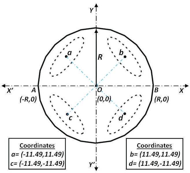
The geometry of the patch of proposed antenna is developed by designing the basic structure of circular patch. The essential parameter of proposed antenna such as radius of patch R=16.25 mm is calculated by using equations (1) and (2) (Balanis, 1997), by taking resonant frequency as f =2.45 GHz. Initial structure of the r conventional circular patch is designed and the elliptical slots are applied at different positions in the geometry to analyze the performance of antenna. The coordinate system of geometry is used to apply the elliptical slots at different positions in the conventional circular patch as shown in Figure 1. Dimensions of elliptical slots such as major axis length and minor axis length along with the tilt angle are shown in Figure 2.
Figure 1. Procedure for Applying the Elliptical Slots in Conventional Circular Patch
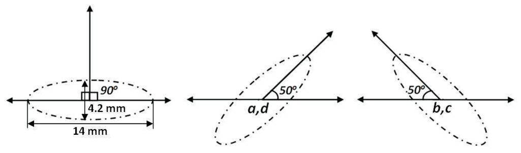
Figure 2. Dimensions and Tilt Angle of Elliptical Slots
The proposed antenna structure is designed and simulated using High Frequency Structure Simulator (HFSS v13) on a rectangular substrate (L × W ). FR4 glass epoxy is s s taken as substrate material with thickness 1.6 mm, dielectric constant 4.4, and loss tangent 0.023. Transmission line with length (L ) and width (W ) is used to F F provide excitation to the radiating patch of antenna. Basic design of proposed antenna with full ground plane is modified to enhance the return loss, gain, and bandwidth at the resonant frequencies over the entire range of 1 GHz to 10 GHz by applying the partial ground plane as depicted in Figure 3. The length of ground plane 'L ' is varied to analyze g wideband behavior of the proposed antenna. Dimensions of the final geometry of proposed antenna with partial ground plane are mentioned in Table 1.
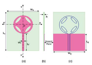
Figure 3. Final Geometry of Proposed Antenna (a) Top View, (b) Side View and (c) Back View
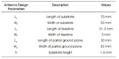
Table 1. Dimensions of Proposed Antenna with Partial Ground Plane
The variation in the resonant frequencies and return loss characteristics are represented in Figure 4, by varying the length of partial ground plane 'L '. Effects of partial ground g plane on the final geometry of proposed antenna are analyzed by varying the values of 'L ' ranging from 26 mm g to 36 mm. When the value of 'L ' is taken as 26 mm, it g exhibits the frequency band of 1.6 GHz with -13.72 dB return loss (S ≤-10 dB) and the corresponding bandwidth 11 of 0.64 GHz (1.31-1.95 GHz). If the value of 'L ' is chosen to g be 28 mm, it exhibits the operating frequencies of 1.5 GHz, 3.4 GHz, and 6.1 GHz having the values of return loss (S ≤ -10 dB) as -18.61 dB, -12.12 dB, and -11.18 dB, 11 respectively with the corresponding bandwidth of 2.80 GHz (1.19-4.00 GHz) and 0.64 GHz (5.83-6.47 GHz). Similarly, when the 'L ' is taken as 30 mm, it operates on g three frequencies of 2.0 GHz, 6.3 GHz, and 7.4 GHz having the values of return loss (S ≤ -10 dB) as -20.83 dB, -18.52 11 dB, and -20.07 dB, respectively with the resultant bandwidth of 3.34 GHz (1.46-4.80 GHz) and 3.01 GHz (5.05-8.06 GHz). Further, if the 'L ' value is selected as 32 g mm, it exhibits frequencies of 2.3 GHz, 4.5 GHz, 6.5 GHz, and 8.2 GHz having the values of return loss (S ≤ -10 dB) as 11 -13.32 dB, -15.33 dB, -15.67 dB, and -34.42 dB, respectively with the subsequent bandwidth of 3.55 GHz (1.84-5.39 GHz) and 2.69 GHz (6.10-8.79 GHz). Moreover, if the 'L ' value is further increased to 34 mm, the antenna g exhibits frequencies of 6.5 GHz and 8.3 GHz having the values of return loss (S ≤ -10 dB) as -12.87 dB and -13.88 11 dB, respectively with the subsequent bandwidth of 0.41 GHz (6.26-6.67 GHz) and 0.54 GHz (8.07-8.61 GHz). Again, if the value of 'L ' is increased to 36 mm, it works only at one g frequency band of 8.5 GHz with return loss (S ≤ -10dB) - 11 11.36 dB and bandwidth of 0.29 GHz (8.33-8.62 GHz). All the variations of the results of 'S' parameters are mentioned in Table 2 for more clarity. By analyzing the 'L ' g parameter, it is observed that this parameter is constrained to 'L ' = 30 mm. At this value, the final g geometry of antenna exhibits wideband characteristics within the frequency range of 1 GHz to 10 GHz. After adjusting the parameter of partial ground plane, the antenna design is finally analyzed and the subsequent return loss curve is presented in Figure 5. It is clear from Figure 5 that the antenna exhibits wide bandwidth of 3.3 4 GHz ranging from 1.46 GHz to 4.80 GHz and 3.01 GHz ranging from 5.05 GHz to 8.06 GHz. The values of return loss are at the acceptable level over the wideband range of frequencies.
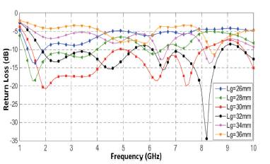
Figure 4. Comparison of Simulated Return Loss (S11) with Different Variations of Ground Length 'L '

Table 2. Variation of Ground Length 'L ' on the g Performance of Proposed Antenna
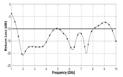
Figure 5. Simulated Return Loss (S ) versus Frequency 11 Plot of Proposed Antenna for 'L ' = 30 mm
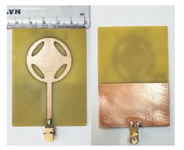
Figure 6. Front View and Back View of Fabricated Prototype of Proposed Antenna
The final geometry of proposed antenna with 'L ' = 30 mm g is fabricated on FR4 glass epoxy substrate as shown in Figure 7 and then tested by using Vector Network Analyzer ( ), Anritsu (MS46322A) ranging from 1 MHz-20 GHz. Comparison of simulated and measured return loss of proposed antenna is shown in Figure 8. It is observed that the measured results of proposed antenna exhibit the bandwidth of 2.518 GHz, 0.67 GHz, 0.83 GHz, 0.93 GHz, and 1.04 GHz ranging from (1.718-4.236 GHz), (4.69- 5.365 GHz), (5.54-6.375 GHz), (6.810-7.739 GHz), and (8.96-10.00 GHz), respectively. Whereas, simulated results of proposed antenna exhibit the bandwidth of 3.34 GHz and 3.01 GHz ranging from (1.46-4.80 GHz) and (5.05- 8.06 GHz), respectively. From Figure 7, it is also observed that the simulated and measured result shows the good approximation at lower frequency band, but some variations are observed as frequency is increased. It may be due to some factors in the physical environment, such as solder bumps, SubMiniature Version A (SMA) connector losses, connecting cable losses, fabrication or measurement errors, parametric variations between simulated and practical models, etc. Basically, these factors are not taken into consideration during simulation environment. The overall performance of proposed antenna for different wireless applications is mentioned in Table 3.
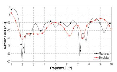
Figure 7. Measured and Simulated Return Loss (S11) versus Frequency Plot of Proposed Antenna

Table 3. Performance of Proposed Antenna for Different Wireless Applications
Antenna efficiency and gain are illustrated in Figure 8; it is observed that the gain of antenna varies from 2.75 dB- 5.62 dB. However, antenna shows the maximum gain of 5.75 dB at 6.7 GHz frequency and minimum gain of 2.14 dB at 4.17 GHz frequency. The radiation efficiency of proposed antenna varies from 0.62 – 0.90 (62% – 90%). Radiation efficiency of the proposed antenna is at acceptable values, it represents the antenna radiated power with respect to the power which is fed to the input port. The radiation patterns for E-plane and H-plane at different resonant frequencies are shown in Figure 9. Radiation pattern describes the direction of maximum radiation of designed antenna at particular frequency band. As expected, the radiation pattern changes to dipole because of modified ground plane. The designed antenna exhibits omnidirectional and linearly polarized radiation pattern at 1.46 GHz, 2.0 GHz, 3.05 GHz, and 7.40 GHz frequency; whereas it is almost omnidirectional at 4.80 GHz, 5.05 GHz, 6.30 GHz, and 8.06 GHz frequency for H-plane. Radiation pattern for E-plane is slightly distorted at 4.80 GHz, 5.05 GHz, 6.30 GHz and 8.06 GHz frequency, but it shows the bi-directional nature at 1.46 GHz, 2.0 GHz, 3.05 GHz, and 7.40 GHz frequency. The proposed antenna changes to the dipole antenna by applying the partial ground plane as depicted from the radiation patterns. This shows that the antenna has maximum radiation in all the directions at the lowest frequency bands of operation.
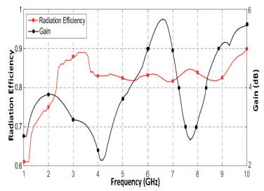
Figure 8. Radiation Efficiency versus Frequency Plot of Proposed Antenna
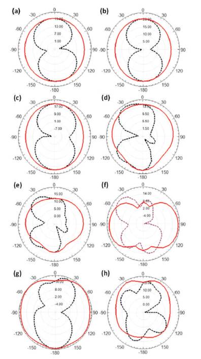
Figure 9. Measured Radiation Patterns of Final Geometry of Proposed Antenna at (a) 1.46 GHz, (b) 2.00 GHz, (c) 3.50 GHz, (d) 4.80 GHz, (e) 5.05 GHz, (f) 6.30 GHz, (g) 7.40 GHz (h) 8.06 GHz
A design of elliptical slots loaded circular microstrip patch antenna for wireless communication has been presented and investigated in this paper. The length of ground plane is varied to attain the desired wideband characteristics. The proposed antenna with ground plane length 30 mm is fabricated and tested on Vector Network Analyzer ( ; the measured results are in agreement with simulated results. Measured results of antenna exhibits the wide bandwidth of 2.518 GHz, 0.67 GHz, 0.83 GHz, 0.93 GHz, and 1.04 GHz ranging from (1.718-4.236 GHz), (4.69- 5.365 GHz), (5.54-6.375 GHz), (6.810-7.739 GHz), and (8.96-10.00 GHz), respectively. The antenna shows good omnidirectional radiation pattern, stable gain, and an acceptable value of radiation efficiency throughout the frequency range of 1-10 GHz. Wideband performance of proposed antenna makes it suitable for different wireless standards, such as DCS, PCS, UMTS, Bluetooth of ISM band, WLAN of IEEE 802.11 b/g/n, WLAN of IEEE 802.11 a/n, WiMAX, X-band for satellite communication, and point to point high speed wireless applications.
In this work, the authors have proposed the circular shaped antenna with partial ground plane loaded with elliptical slots. The different types of patch geometry and slots, such as rectangular; polygon, elliptical, ring, etc., can be used for future work. Moreover, different optimization techniques, such as Genetic Algorithm (GA), Particle Swarm Optimization (PSO), and Bacteria Forging Optimization (BFO) can also be used in future to analyze the performance of designed antenna in future. Defected ground plane and ground plane with slots/stubs are used in future to enhance the performance in terms of bandwidth, gain, and reflection coefficient.