Figure 1. Patch Antenna
A coaxial fed tri-band model has been proposed for microwave access, which is typically involved in the applications of L and S band that combines Wireless Local Area Network (WLAN) and Worldwide Interoperability for Microwave Access (WiMax). The proposed model has a size of 20×20×1.66 mm3 with FR4 epoxy as a dielectric substrate, which has a relative permittivity of 4.4. It has symmetrical slots on the conducting patch which are C-shaped and also has a rectangular strip slot in ground plane, so that tri-band can be obtained. It is mainly designed to work within 1 GHz to 8 GHz. The designed structure is simulated by High Frequency Structure Simulator (HFSS) and the peak value of return loss, 27 dB, is obtained at 3.5 GHz frequency. The simulated results depicted that the proposed antenna will respond well over 2.38-2.43 GHz, 3.43-3.56 GHz and 5.5-5.8 GHz frequency band.
In the growing age of technology, antennas are playing an important role in wireless communication (Majumder, 2013; Roy and Bhunia, 2012). For better transmission, the antennas should have good bandwidth as well as compact size, light weight and should be easily integrated. Microstrip antennas are fulfilling all these characteristics along with good radiation in free space (Chu and Ye, 2010; Carver and Mink,1981; Pozer, 1982). For efficient radiation, antennas should be the length of λ/2 (Morshed et al., 2010). Various methods are used to enhance the bandwidth like feeding techniques, different slots in patch and ground structure etc. (Lee et al., 2011; Wong and Chen 1997; Mak et al.,1999). Among all these methods, coaxial feeding is the best method. To achieve the multiband antenna, bend slots are generally used (Vani et al., 2006; Garg, 2001). It enhances the performance of antenna without affecting its size. These structures are easy to design and can be fabricated on chip.
Creating a slot in ground plane is an effective method to By enhance the bandwidth without increasing the size of antenna (Garg, 2001). Along with bandwidth, other parameters like gain, axial ratio, and return loss also increases. Creating a slot increases the path current, hence current travels extra path as compared to the plane without slot. Defected ground structure is a cascaded configuration and is responsible for multiple resonances. Using slots in ground plane, characteristics of transmission line can be changed. Ground slots are used for the slow wave effect in microstrip antenna so that downshift of resonance frequency can be achieved. By using this method, multiband antenna are easily achieved (Dey and Mittra, 1996; Lee et al., 2005).
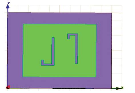
Designed antenna is printed on FR4 substrate material having 0.04 dielectric constant and 0.02 loss tangent with 1.6 mm thickness. This antenna consists of two C-shaped bend slots in addition with ground slot with one rectangular strip. The dimensions of antenna are given below.
Dimension= 20×20 mm2 , Patch = 14×14 mm2 , Length of Slot = 11 mm, Width of Slot = 0.5 mm, Rectangular Strip = 16 mm with Strip Length = 12 mm and Width of Strip = 1 mm.
Coaxial feeding is used in this antenna design. Inner radius of circle is 0.5 mm and outer radius is 1 mm. Figure 1 shows the design of patch antenna. The ground side of Antenna is shown in Figure 2.
Figure 1. Patch Antenna
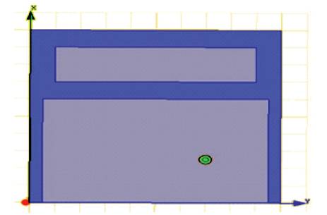
Figure 2. Ground Side of Antenna
To design multiband antenna, bend shaped slots are generally used because it increases the current path, which in turn increases the return loss. The feeding method used is easily fabricated on the chip.
The designed antenna is simulated in High-Frequency Structure Simulator (HFSSv.15) and its various parameters are studied. Figure 3 gives the return loss parameters for various frequency ranges.
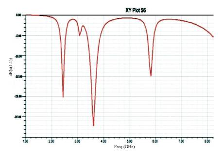
Figure 3. Return Loss Curve
The graph in Figure 3 shows the return loss of the antenna at resonant frequencies 2.4 GHz, 3.5 GHz, and 5.5 GHz. The return loss at 2.4 GHz is 21 dB, 3.5 GHz is 27 dB and 5.5 GHz is 17 dB.
The other parameter considered is Voltage Standing Wave Ratio (VSWR). Figure 4 shows the VSWR curve of the designed antenna. The value of VSWR for any antenna should lie between 1 to ∞, but practically it lies between 1 and 2 for better transmission. For the above mentioned antenna, the value of VSWR is below 2 at three resonant frequencies. To decide the range of antenna, its radiation pattern is important; whether it is unidirectional or omnidirectional antenna. Figure 5 represents the radiation pattern of antenna.
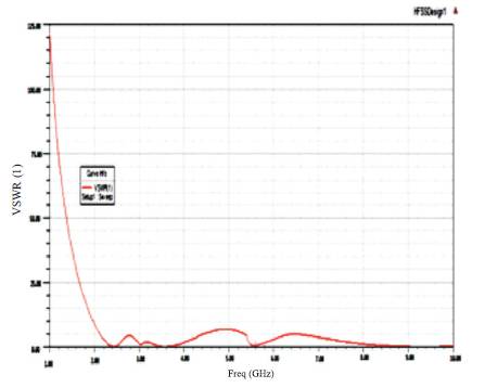
Figure 4. VSWR Curve of Antenna
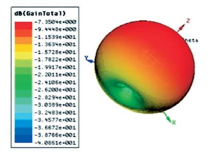
Figure 5. Radiation Pattern of Antenna
From Figure 5, it can be seen that the designed antenna is an omnidirectional antenna i.e. it radiates in all direction uniformly. The other parameter which comes from the radiation pattern is polar plot. It is a 2-D plot plotted between θ and Φ. It has many concentric circles, which share the same centre. The outer circle represents the θ value whereas the inner circle tells about the gain of the antenna. Figure 6 represents the polar plot of antenna plotted at different frequencies.
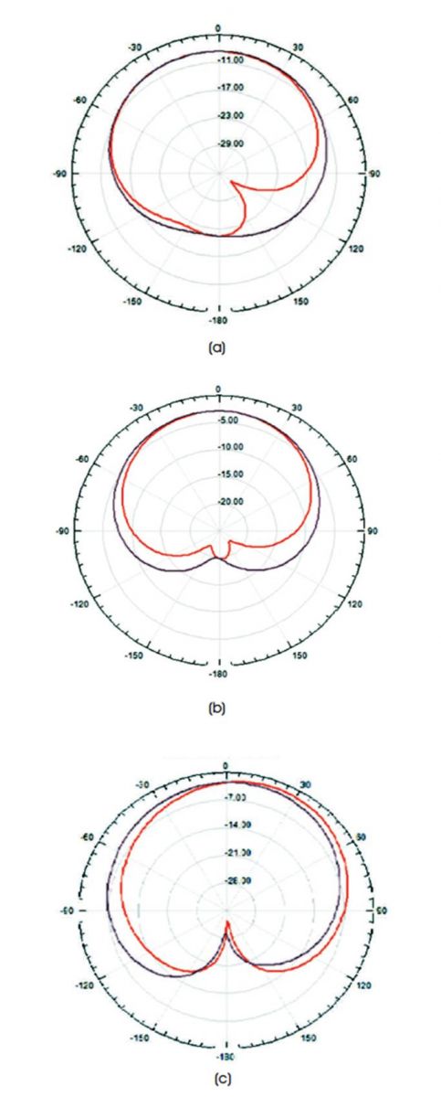
Figure 6. Polar Plot at (a) 2.4 GHz, (b) 3.5 GHz, (c) 5.5 GHz
In this paper, the authors have examined the tri-band antenna which is resonating in L and S band. The proposed antenna has an overall dimension of 20×20×1.6 mm3. The designed antenna has a C-shaped slot in radiating patch as well as a rectangular strip slot in ground plane. By using these slots, tri-band operation is easily achieved. This proposed antenna easily covers the WLAN and WiMAX frequency bands. The return loss of antenna is 21 dB at 2.4 GHz, 27 dB at 3.5 GHz and 16 dB at 5.5 GHz. This antenna is also used for mobile communication due to its omnidirectional radiation pattern and other wireless communication systems. Hence, it is concluded that the designed antenna has a simple structure with effective results like return loss and radiation pattern with polar plot.