Figure 1. Front View of Antenna without Notch Structure
This paper represents the compact Ultra Wide Band antenna with notch characteristics. The proposed antenna consists of stubs, slots, and strips to create the notch characteristics. To reduce the size of antenna and to get the better rejection characteristics, it uses notches at the ground structure and slot techniques. This antenna is used to eliminate the potential interference caused by narrow band services along with reduction in size of antenna. This antenna uses T-shaped stub, inverted U-shaped strips near the feedline, and T-shaped slot at the edge of patch. VSWR of antenna without notch band is nearly equal to 2. This antenna gives the rejection for WiMAX band (3.3-3.7 GHz), WLAN band (5.725-5.825 GHz), and Xband satellite communication (7.250-7.745 GHz).
Ultrawideband technology is becoming the most prominent technology from the past few decades because of its features, such as high data rate, low power usage, and having a wide spectrum. Ultrawideband spectrum ranges from 3.1-10.6 GHz, use of this spectrum is authorized by Federal Communication Commission (FCC) on Feb 14, 2002 [1].
Ultrawideband spectrum has very large bandwidth, therefore it co-exist with some other narrow band services, such as WLAN operating at (5.15 - 5.35 GHz, 5.725 - 5.825 GHz), WiMAX (3.3 - 3.7 GHz), C-band (3.7 - 4.2 GHz) and X-band satellite communication (downlink band 7.250 - 7.745 GHz, uplink band 7.900 - 8.395 GHz) causes interference in UWB system. Interference may be two types, caused by UWB on the victim of narrow band services and caused by narrow band services on the victim of UWB. Interference caused by narrowband services on the victim of UWB is the severe problem. There are many techniques to eliminate this problem by introducing filter structure on the radiating patch or near the feedline of antenna. Following study shows that by introducing slot, stub, and resonator [2], rejection characteristics can be obtained, such as etching Ushaped slot [3, 7], L- shaped slot [4], T-shaped [8,10], and C-shaped [8] slot on the radiating patch of antenna. Introduction of circular stub is given in [5]. Use of strip line [6] is also the way to reject narrow band services. Use of slot technique also helps in the reduction of the size of antenna as the size of antenna is also the important parameter for designing of antenna. Reduction in size comes at the cost of the performance of the antenna which can be overcome by using notch structures at its ground plane and it also help in reducing the size of antenna.
In this letter, T- shaped stub is introduced on the radiating patch to create notch. Second notch is created by introducing pair of inverted U-shaped parasitic strips near the feedline and by etching T-shaped slot at the edge of radiating patch third notch is obtained. This paper basically works on to create notch characteristics along with the reduction of size of antenna. The proposed antenna is designed and simulated on the HFSS (v.13). Notch bands are obtained at the centre frequencies of 3.5 GHz, 5.8 GHz, and 7.6 GHz.
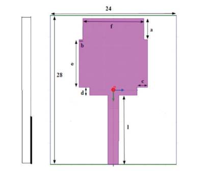
The proposed antenna is designed on FR4 substrate with dielectric constant of 4.4 with thickness of 0.8 mm. Antenna is fabricated on substrate size of 28 × 24 mm2 . Bevelled ground plane with notch is fabricated on the bottom of substrate and radiating patch along with feedline is fabricated on upper side of substrate. All the specification of radiating patch and ground plane is shown as, a= 4 mm, b= 0.7 mm, c= 2 mm, d=1.5 mm, e= 9 mm, f=11.6 mm and l= 13 mm, k1= 7 mm, k2=6 mm, h= 12 mm, c1=1.5 mm, c2= 1.8 mm, and the gap between the ground plane and the radiating patch is 0.5 mm.
Figure 1 and 2 represents the geometry of front view of antenna and the back view of antenna without any notch structure, respectively.
Figure 1. Front View of Antenna without Notch Structure
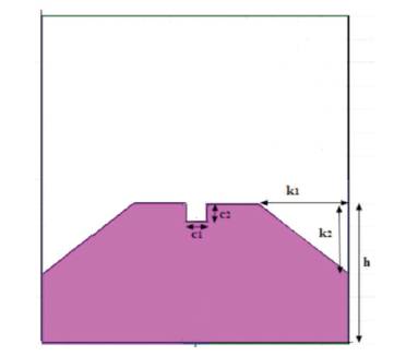
Figure 2. Geometry of Ground Plane
In the proposed antenna, two square slots are cut at the bottom edges of the radiating patch and two rectangle shaped slots are cut at the upper edges of the radiating patch. Ground plane of the antenna is bevelled for the smooth transition of resonant mode and notch is also introduced in the ground plane, which is helpful to get the desired radiation pattern and to reduce size.
VSWR plot of the ultrawideband antenna without any notch structure is shown in Figure 3. The plot represents VSWR value for the entire UWB frequency spectrum, VSWR for antenna is less than or equal 2.
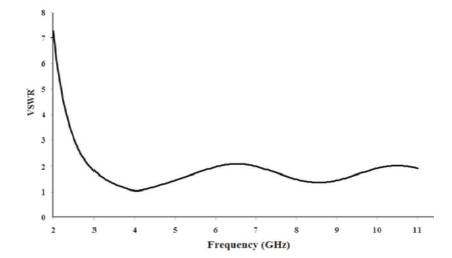
Figure 3. VSWR of Antenna without Notch Structure
The proposed antenna acts as dipole antenna (Figure 1 and 2). Radiation pattern of antenna without any notch structure is shown in Figure 4 and Figure 5. Figure 4 depicts the omnidirectional radiation pattern in H-plane and Figure 5 represents the radiation pattern in E-plane.
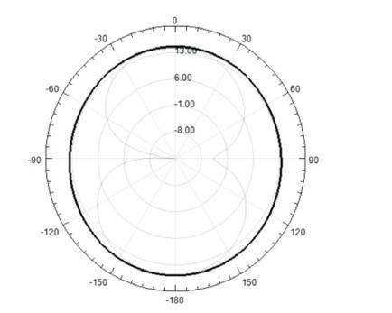
Figure 4. Radiation Pattern of Antenna without Notch Band in H- Plane
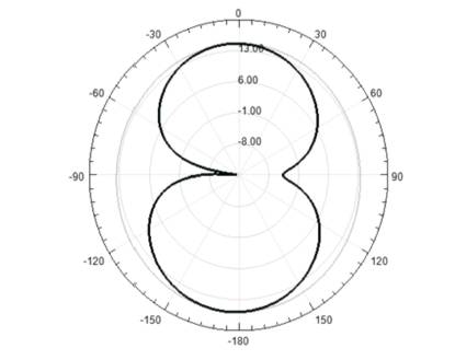
Figure 5. Radiation of Pattern of Antenna without Notch Band in E-plane
Triple notches in ultrawideband antenna is obtained by introducing T-shaped stub, T-shaped slot on the radiating patch, and use of parasitic strips near feedline.
Dimensions of antenna with notch structure (Figure 6) is given as, ts1=1.8 mm, ts2=3.8 mm, u1= 5 mm, u2=6.3 mm, t1=7 mm, t2= 7 mm, y= 8 mm, p= 1mm, q= 0.8 mm, r=0.7 mm, w=2 mm, zz=3 mm, j= 3.5 mm.
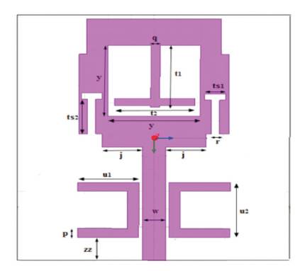
Figure 6. Front View of Antenna with Notch Structures
The notched frequency antenna does not radiate out because the resonance frequency current concentrated around the notch structure causes the antenna not to radiate.
Dimension of ground plane of antenna is m= 0.9 mm, n=1mm is shown in Figure 7. The use of notch on the ground plane helps to obtain desirable performance and it also helps in reduction of size of the antenna.
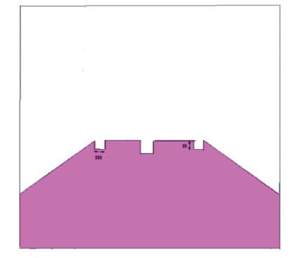
Figure 7. Geometry of Ground Plane of the Proposed Antenna
The proposed antenna structure helps to obtain notched band at the centre frequencies 3.5 GHz, 5.8 GHz, and 7.5 GHz, respectively.
Radiation pattern is the graphical depiction of the antenna gain that how much antenna can radiate out. Figure 8 represents the radiation pattern of antenna at the notch frequencies 3.5 GHz, 5.8 GHz, and 7.6 GHz, respectively.
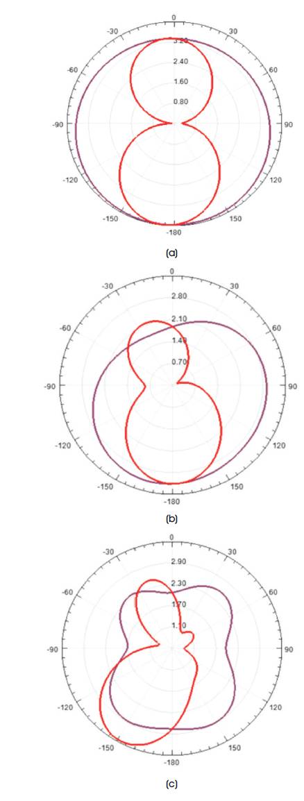
Figure 8. Radiation Pattern of Antenna at Notched Bands, (a) 3.5 GHz, (b) 5.8 GHz, (c) 7.6 Ghz
From the radiation pattern plot, we can depict that antenna gives distorted result with less gain at the notch frequencies that is antenna doesn't radiate out at the notch frequencies. From the radiation pattern plot, we can depict that antenna gives distorted result with less gain at the notch frequencies that is antenna doesn't radiate out at the notch frequencies.
Figure 9 represents the radiation pattern of the antenna, without notch band, where it gives high gain in comparison with notch band structure (Figure 8).
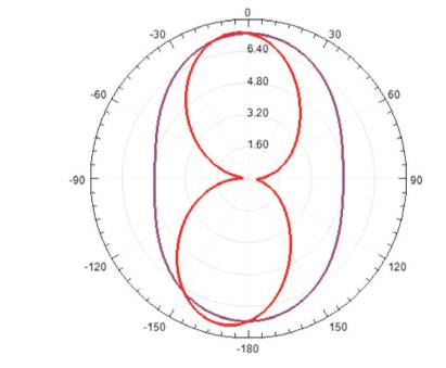
Figure 9. Radiation Pattern of Antenna without Notched Band at 6.5 GHz
VSWR of the antenna with notch structures is shown in Figure 10, it shows the first notch at the centre frequency of 3.5 GHz for WLAN band, second notch at centre frequency 5.8 GHz for WiMAX band, and third notch at the centre frequency of 7.6 GHz for X-band satelite communication.
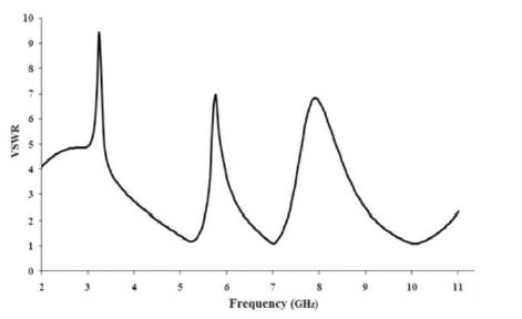
Figure 10. Simulated VSWR of Antenna for Triple Band Notch Characteristics
From Figures 8 and 9, it can be concluded that the antenna provides better gain at other than the notch frequencies means the power intensity of antenna with the notch frequencies is very low in comparison to other frequencies.
These three notches are obtained by using T-shaped stub, inverted pair of U-shaped strip, and T-shape slot with VSWR of 9.5 at 3.5 GHz for the rejection of WiMAX band, VSWR 6.9 at 5.8 GHz for WLAN band and VSWR 7 at 7.6 GHz for X-band satellite communication, respectively.
A compact ultrawideband antenna with notch structure has been simulated. Size of the antenna is 28 × 24 mm2 with three rejection bands. Table 1 gives the comparison of the proposed work with other research works, which is basically related to the size of antenna and the triple notch characteristics, that is the size of the proposed antenna is less in comparison to other works and it gives three notch band at resonant frequencies or notch frequencies. Three rejection bands, WLAN band with centre frequency 3.5 GHz obtained by using T-shaped stub, WiMAX band with centre frequency 5.8 GHz is obtained by a pair of inverted Ushaped strips, and the X-band satellite communication with centre frequency 7.6 GHz is obtained by using a pair of T-shaped slots.

Table 1. Comparison of this Work with Other Research Works