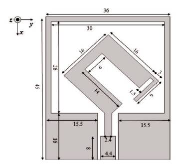
Figure 1. Geometry of the Proposed Triple-band Antenna (Unit in mm)
In this paper, a small-size inverted U-shaped structure is presented for designing a triple-band Circularly Polarized (CP) antenna which has a single metallic layer. A micro-strip Coplanar Waveguide (CPW) feed is given. The proposed antenna has a rectangular ground plane and a radiating patch that has an inverted U-shaped, and inverted L-shaped structure that creates three bands in X-band operating at 8.0 / 9.2 / 9.7 GHz frequency bands and has less than -10 dB returnloss bandwidths. The antenna also provides CP modes at 7.1 / 8.5 / 9.9 GHz. The 3 dB axial-ratio bandwidths are 486 MHz centered at 7.1 GHz, 178 MHz centered at 8.5 GHz, and 190 MHz centered at 9.9 GHz. The proposed antenna operates at frequencies 8.0 / 9.2 / 9.7 GHz with VSWR<2.
Now-a-days, wireless communication systems for short and long range are becoming very essential, such as wireless LAN, Bluetooth, amateur radio, radar, downlink of the Xband satellite communication at 7.5 GHz, military requirement for earth exploration satellite (downlink) purposes in the band 8.025-8.4 GHz, military requirement for land, airborne and naval radars (Radio location) in band 8.5-10.5 GHz, etc. But the integration of multiple antennas, to implement the multiple frequency bands on receiver, may cause mutual coupling due to which overall performance may decrease.
To reduce the above problem, an antenna with single radiator performing multi-functions can be better. A Circularly Polarized (CP) antenna can be helpful in this regard because CP antennas have many advantages, such as flexibility between receiver and transmitter, reduces multi-path fade effect [1], high data rate capacity, and provides wide signal coverage [2]. To achieve this, various research works have been done on CP antennas [3-13]. Various techniques, like truncated corner square slot [3], multilayer stacked square patches [4], rotated U-shaped strip and patch [5, 6], corner feeding [7], and inverted Lshaped slots [8, 9], hexagon geometry [10] and many more, have been preferred to achieve CP modes.
In this paper, the authors have presented a CPW-fed antenna with circular polarization for X-band application. A micro-strip Coplanar Waveguide (CPW) feed is given as it has many preferable features like less circuitry and less installation space [5], no soldering points, fabrication is easy, easy to integrate with monolithic microwave integrated circuits, and a simple configuration with a single metallic layer [11]. The design of the proposed antenna is simple and less complex than the CP antennas reported previously. The antenna features the bandwidths of -10 dB return loss and 3dB axial ratio.
Figure 1 shows the geometry of the proposed antenna with its dimensions in mm. The antenna is designed on a 45 x 36 mm2 FR-4 substrate with dielectric constant of 4.4, loss tangent 0.02, and a thickness of 1.00 mm. The radiating patch consists of an inverted U-shape and inverted L-shape rotated at an angle of 450 to achieve the three CP modes.The micro-strip CPW feed line width is 4.4 mm and gap width is 0.3 mm to achieve 50 Ω impedance.
Figure 1. Geometry of the Proposed Triple-band Antenna (Unit in mm)
The simulation work and performance of the proposed CP antenna was carried out by the software ANSYS Electromagnetics Suit 16.2.
Figure 2(a) shows the simulated result of the return loss at frequencies in X-band at 8.0 GHz, 9.2 GHz, and 9.7 GHz, which have more than -10 dB return loss. The bandwidths are 699 MHz (7.632 GHz-8.301 GHz) 8.7% centered at 8.0 GHz, 414 MHz (8.880 GHz-9.294 GHz) 4.5% centered at 9.2 GHz, and 378 MHz (9.516 GHz-9.894 GHz) 3.9% centered at 9.7 GHz. Figure 2(b) shows simulation result of axial ratio of the proposed antenna, which shows three CP modes at 7.1 GHz, 8.5 GHz, and 9.9 GHz in the X-band frequency range. The 3-dB axial-ratio bandwidths are 486 MHz centered at 7.1 GHz, 178 MHz centered at 8.5 GHz and 190 MHz centered at 9.9 GHz. The inverted U-shape structure provides two CP modes at 7.1 GHz and 8.5 GHz. The third CP mode was achieved by the inverted L-shape structure in the radiating patch. This improves the performance of the antenna.
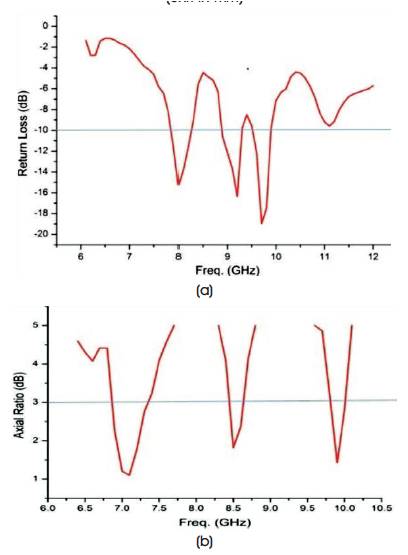
Figure 2. Simulated Result of (a) Return Loss, and (b) Axial Ratio
Figures 3(a) and 3(b) show the LHCP and RHCP radiation pattern of the proposed antenna, respectively at 8.5 GHz frequency. The level of both LHCP and RHCP is well below 15 dB. Figure 4 shows the VSWR of the proposed antenna which is below 2 at the operating frequency ranges centered at 8.0 GHz, 9.2 GHz, and 9.7 GHz.
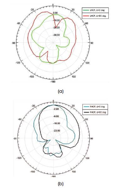
Figure 3. Simulated Radiation Pattern of Proposed Antenna
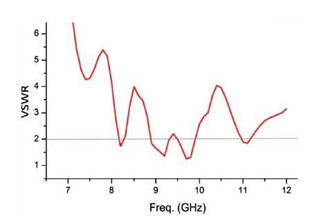
Figure 4. Simulated VSWR Result
In this paper, a simple triple-band circularly polarized antenna with CPW feed was proposed. The proposed antenna operates at three frequency bands which are (7.632 GHz - 8.301 GHz), (8.880 GHz - 9.294 GHz), and (9.516 GHz - 9.894 GHz) in X-band. Two CP modes at 7.1 GHz and 8.5 GHz were achieved by inverted U-shape structure, and the third CP mode at 9.9 GHz was generated by introducing an inverted L-shape structure. A micro-strip CPW feed was given to have a simple configuration with a single metallic layer. The antenna has achieved bandwidths of -10 dB return loss and 3 dB axial ratio. The proposed antenna can be used for X-band satellite communication system e.g., for fixed-satellite service and mobile-satellite service military radio spectrum.