[1]
In this paper, an ACS-fed Multiband antenna is presented. The resulting antenna resonates at 2.4 GHz, 3.5 GHz, 5.5 GHz covering the WLAN and WiMAX operation bands. The overall dimensions of antenna is 19×21 mm printed on FR4 substrate material of 4.4 dielectric constant and 1.6 mm thickness. The proposed antenna follows the uncomplicated design, compactness, and easy fabrication. The details of antenna and results are discussed in this work. The antenna is designed using HFSS v13.
In wireless communication systems, demand of high data rates and higher band width has been increased. To consummate these demands, multiband antennas are popular to cover multiple frequency bands [1-4]. These antennas have simple structure, compact in size, and can be easily fabricated on chip.
Previously antennas are designed using CPW feeding, which consists of two ground plane and one signal strip. The downside of this feeding is it occupies more area on chip. To overcome this disadvantage, asymmetric coplanar strip feed is generally used. It has only one ground plane and one signal strip. The occupied area is reduced to 50% from the previous one.
The other techniques to reduce the size of antenna are cutting a slot on ground plane to shift the frequency towards the lower side. In other words, the lower frequencies are easily covered by DGS. DGS is a cascaded configuration and responsible for the multiple resonances. The slot gap gives the capacitive effect and the narrow line gives the inductive effect [5]. Using DGS, the characteristics of transmission lines have been changed. The bent slots are used to increases the path current in antenna slot, having a length of half of the guided wavelength at the particular frequency [6-8].
In this paper, an ACS-fed multiband antenna has been discussed, having gradual change and multiple slots on ground plane. The suggested antenna resonates at three frequencies 2.4 GHz for Bluetooth, 3.5 GHz for WiMAX, and 5.5 GHz for WLAN operation bands.
An asymmetric coplanar strip feeding is used, which has a diagonal edge on ground plane and multiple L-slots. One L-slots is cut on the signal strip of feeding line. The length of the slots should be quarter of the wavelength calculated at particular frequency.
Feeding of antenna is indispensable part for achieving good results. To resonate an antenna at particular frequency, the characteristics impedance should be matched to the load impedance [9]. The characteristics impedance of asymmetric coplanar strip is defined as,
where εeff is effective dielectric constant.
where εr is relative dielectric constant.
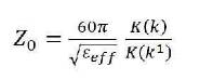
Figure 1 shows the geometry of antenna, printed on FR4 substrate material of 1.6 mm thickness, 4.4 dielectric constant, and 0.02 loss tangent. The dimension of antenna is 19×21 mm2 . The width of signal strip is 3 mm and a gap of 0.5 mm between ground plane and signal strip having 50Ω characteristics impedance.
Figure 1. Antenna Geometry
One end is open for ground L- slots, they are called open ended slots, length of the slots is quarter of the guided wavelength at resonating frequency. Generally, chamfer change is adopted for wide band antenna. Therefore, bevelled edge introduced at the ground plane.
The width (w)= 19 mm, length (L) = 21 mm, slot L1 = 19mm, L2= 15 mm, L3 = 9 mm, gradual width is 2.5 mm and gradual length is 5 mm.
Figure 2 shows the simulated result of return loss of antenna which is -25 dB at 2.4 GHz, -27 dB at 3.5 GHz, and -17.50 dB at 5.5 GHz. These frequencies are used in WLAN and WiMAX applications.
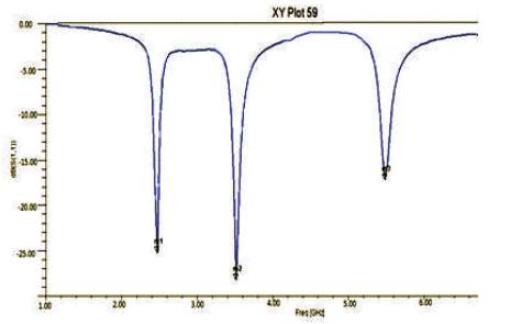
Figure 2. Return Loss Curve of Proposed Antenna
There are diverse parameters to describe the antenna performance. Figure 3 represents the VSWR characteristics of above antenna. The overall VSWR at all frequencies lies between 1 and 2, which is a considerable value for any antenna. The applications of any antenna can be decided by its radiation pattern. Figure 4 is the 3-D radiation pattern of the antenna, which is omni directional. Hence this antenna can be used for mobile communications systems. The red colour tells the radiation intensity of antenna. Hence the gain of antenna is about 2.12 dBi at 2.4 GHz and 3.5 GHz.
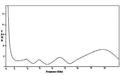
Figure 3. VSWR Parameter of Antenna
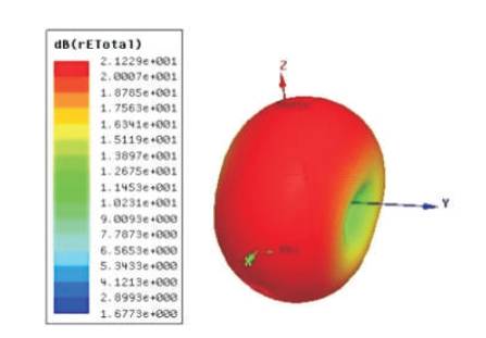
Figure 4. 3-D Polar Plot of Antenna
2-D polar plot is also another parameters which tells about the antenna performance. It has a circular plot with two angles, one is θ and other is Φ. The outer circle represents the direction that is in which direction antenna is radiating. The inner circles tells us about the gain of the antenna. Figures 5 (a)-(c) show the polar plot of resulting antenna.
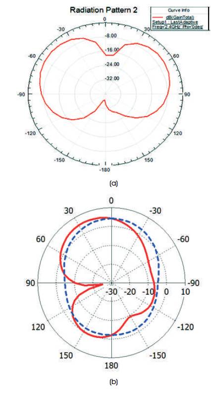
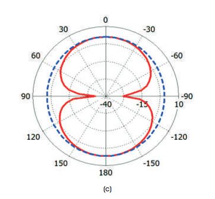
Figure 5. (a) Polar Plot calculated at 2.4 GHz, (b) Polar Plot calculated at 3.5 GHz, (c) Polar Plot calculated at 5.5 GHz
The authors have examined the asymmetric coplanar strip multiband antenna for wireless communication. The resulting antenna easily cover the three wireless frequencies 2.4 GHz, 3.5 GHz, and 5.5 GHz. This compact antenna has overall dimensions is 19×21 mm2 . These printed antennas are less flimsy, easily integrated, and immoderate. The above antenna consists a defected ground plane with multiple resonance characteristics. These antennas are dispensable to quad, penta, or hexa band. It has been concluded that printed antennas are more dense, adaptable and easy integration antennas for multiple operation bands and used in mobile communication due to it's omni directional radiation pattern and all wireless communication systems.