The objective of this paper is to design and perform analysis of PIFA in order to obtain the required performance characteristics for mobile and UWB applications. Simulation and analysis were carried out by high frequency structure simulator, HFSS. The proposed antenna covers a wide frequency range from 0.67 GHz to 11GHz. It operates at LTE700 MHz, GSM (800-900 MHz), GPS (1.22 and 1.57 GHz), DCS (1.8 GHz), PCS (1.9 GHz), Wi-Fi and Bluetooth (2.4-2.5 GHz), 5 GHz WLAN and the major part of UWB frequency range The proposed antenna consists of a rectangular patch, rectangular parasitic element, inverted-L Shaped parasitic element, slots in ground plane which produces low frequency resonance and thick feeding terminal. The antenna design parameters are varied to study its effect on performance of the proposed antenna. The proposed antenna has a flat and simple structure, which can be easily implemented.
UWB technology is rapidly growing in demand for the use in several present and future applications. The Federal Communications Commission (FCC) approved the UWB frequency range from 3.1 GHz to 10.6 GHz in 2002 for commercial use [1]. Antenna also plays an important role in UWB system. However, design of UWB antenna requires antenna having very broad impedance bandwidth. The basic requirement of UWB antennas is that, it should be able to operate over frequencies released by the FCC. UWB applications include accurate positioning (through wall radar, tracking), satellite communications, high quality wireless video, air traffic control, medical imaging, etc. The PIFA has higher directivity than the planar monopole antennas. The Planar Inverted- F Antenna (PIFA) design is one of the most promising antennas to meet these requirements.
PIFA is an extended form of inverted-F antenna, in which the radiating wire is replaced with planar surface. The planar Inverted-F Antenna (PIFA) is one of the widely used antenna in mobile phones today. A PIFA consists of a ground plane, rectangular patch, feed line, and short pin. It operates at a resonant length of λ/4, and is highly conducive to a small and simple design, thus suited for the use as an internal antenna [2, 3].
Its use is increased due to small size, simple manufacturing, high efficiency, reliable radiation pattern and low Specific Absorption Rate (SAR).
Several techniques are used for the bandwidth enhancement of PIFA [5-7]. These techniques include increasing the feeding plate and short strip width, adding parasitic elements such as rectangular parasitic element, inverted-L-shaped parasitic element, adding slots in the ground plane which produces lower frequency resonance, and the same types of slots that can be added in the patch also [8]. Finally, a combination of these techniques is used for enhancing the bandwidth of PIFA and their effects are studied [9-11].
The antenna reported in [4] covers a very large bandwidth from 817 MHZ to 11.5 GHz with S11<-6 dB except in the interval from 3.36 to 3.72 GHz, where optimization was difficult. It consists of a rectangular parasitic element, ground plane, feed strip, radiating patch and thick feeding terminal. It operates at cellular (800-900 MHZ), GPS (1.22 and 1.57 GHz), DCS (1.8 Ghz), PCS (1.9 Ghz), LTE (except the North American 700 MHz band and the frequencies between 2.4 and 2.6 GHz), the 5 GHz WLAN and a considerable part of the UWB frequencies. In this paper, planar inverted-F antenna is designed with parasitic elements and slots on the ground plane. The new antenna has a lower profile of 4 mm that is entirely adaptable with the size restrictions imposed by smartphones. The penalty incurred by using a lower profile is that, the Figure of merit S11 < -10dB is diminished to S11 < -6dB. However, the new antenna presented in this paper satisfies the criterion of S11 < -10 dB in important parts of its bandwidth.
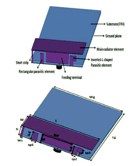
The geometry of the proposed PIFA is shown in Figure 1. The antenna is constructed with rectangular patch, ground plane, rectangular parasitic element, inverted-L shaped parasitic element, short strip and thick feeding terminal. Ground plane is 100×40 mm2 close to the commonly found smartphone dimensions. There is a FR4 substrate of thickness 1mm and permitivity 4.4. Substrate is between the ground plane and feed plate. The antenna height is 4 mm and the space between the top plate and the substrate is filled with air (free space). Thick feeding terminal is used, which provides a single, very large bandwidth and the slots are used in ground plane. Slots help to increase the electrical size without any increase in the physical size.
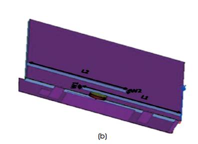
Figure 1. Geometry of Proposed Antenna (a) Front View (b) Back View
Slots are placed just below the rectangular patch, but one of the slot is outside the boundary of the rectangular patch. Detailed dimensions of the proposed antenna is shown in Table 1.
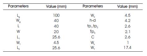
Table 1. Detailed Dimensions of the Proposed Antenna
The design of the proposed antenna and its parametric study were carried out by High Frequency Structure Simulator (HFSS). It is a mostly used software for designing of antennas and filters. Performance, capacity and its accuracy is very good hence this software is widely used for simulation purposes. The HFSS solution process overview is described in some steps.
The first step includes drawing of the geometric model of the structure that is to be analyzed. The next step is selection of the materials that the various drawn objects are made of assigning an accurate definition of boundaries for the structure, such as, perfect magnetic or electric conductor. In HFSS, a port or a voltage source needs to be defined to excite the structure. This is done as a part of boundary definitions. Once the structure is completely modeled, the solution is set up.
A study is carried out by changing one parameter at a time to observe its effects on the characteristics of the PIFA, while all other parameters are held constant. Feed position is varied from 21.1 mm to 21.8 mm and the best result is shown at 21.8 mm in Figure 2.
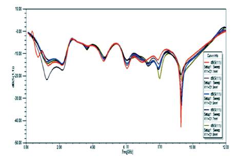
Figure 2. Simulated S11Plot with Different Feed Positions
Slot size in ground plane is varied from 22 mm to 25.6 mm and the best result is shown at 25.6 mm in Figure 3.
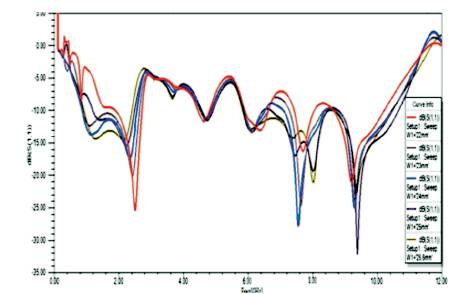
Figure 3. Simulated S11Plot with Variation of Slot Size in Ground Plane
Position of parasitic element is varied from 28 mm to 32 mm and the best result is shown at 30 mm in Figure 4.
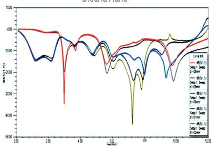
Figure 4. Simulated S11 Plot with Different Positions of the Parasitic Element
Height of the radiating plate is varied from 3.4 mm to 4 mm and the best result is shown at 4 mm in Figure 5.
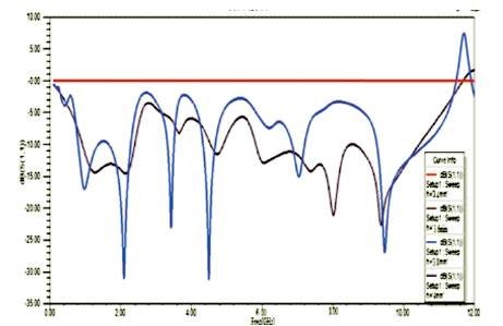
Figure 5. Simulated S11plot with Different Patch Height
The simulation of the proposed antenna in this paper is done with the help of High-Frequency Structure Simulator (HFSS). The width of shorting pin, width and position of the feeding terminal, width and length of the slots in ground plane, position of the rectangular parasitic element and the inverted-L-shaped parasitic element were modified for a required bandwidth.
Simulated return loss of the proposed antenna is shown in Figure 6. The main structure of PIFA controls the first resonance and lower frequency. Addition of rectangular parasitic element creates resonance at 8.01 GHz. Further addition of inverted-L-shaped parasitic element creates resonance at 9.36 GHz and a wide bandwidth is observed.
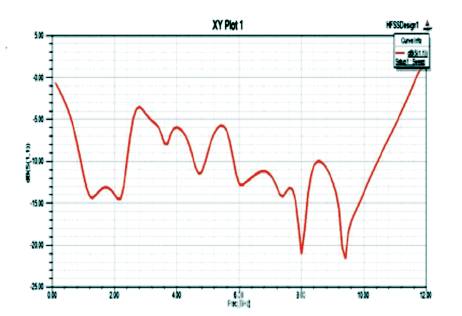
Figure 6. Simulated S11 Plot of the Proposed Antenna
The proposed antenna fulfills the criterion of S11 <-6 dB in the entire frequency band from 0.67 GHz to 11 GHz, excluding the band from 2.6 GHz to 3.3 GHz. The optimization of this part of band was difficult and hence simulated results are close to the defined limit. The proposed antenna covers LTE 700 MHz, GSM (800-900 MHz), GPS (1.22 and 1.57 GHz), DCS (1.8 GHz), PCS (1.9 GHz, WiFi and Bluetooth (2.4-2.5 GHz), 5 GHz WLAN and the major part of UWB frequency range.
Simulated radiation patterns are shown in Figure 7. Radiation patterns of the proposed antenna is observed in E-Plane and H- Plane at 1.88 GHz, 5.9 GHz, 8.01GHz and 9.36 Ghz. The observed radiation patterns are quasi omni directional.
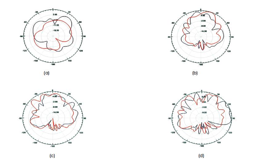
Figure 7. Simulated Radiation Patterns of the Proposed Antenna in both E Plane and H Plane at (a) 1.88GHz, (b) 5.9GHz, (c) 8.01GHz, and (d) 9.36GHz
This paper proposed a new ultra-wideband PIFA antenna by using an inverted-L shaped parasitic element, rectangular parasitic element, addition of slots in ground, short strip, radiating patch and thick feeding terminal. With advancement in wireless communication, there is need of single antenna that can cover wide frequency band for mobile applications and future UWB services. Here in this paper, two designs are introduced for bandwidth improvement of PIFA. With addition of two parasitic elements, which are rectangular parasitic element and inverted-L-shaped parasitic element. The proposed antenna covers a wide frequency band, which includes LTE 700 MHz, Cellular (800-900 MHz), GPS (1.22 and 1.57 GHz), DCS (1.8 GHz), PCS (1.9 GHz), Bluetooth and WiFi (2.4-2.5 Ghz), 5 GHz WLAN and a major part of UWB (3.3 to 11 GHz). This antenna covers the frequencies between 0.67 GHz and 11 GHz with S11 <-6 dB. Extensive parts of this bandwidth achieves a better parameter of S11<-10 dB. Addition of rectangular parasitic elements create resonance which improves the bandwidth. Further addition of inverted-L-shaped parasitic element creates another resonance and helps in achieving a large bandwidth. This proposed antenna fulfills the need of single antenna for mobile and UWB applications. In addition, the detailed parametric analysis of the designed antenna is also carried out to study the effects of various antenna parameters. The proposed antenna is capable of operating with mobile and UWB applications. The proposed PIFA has a flat and simple structure that can be easily implemented .