Figure 1. Elements of an Optical Network
In this work, the authors have reviewed the basic concepts of optical fiber network. They describe its key feature and its rapid advancement in the telecommunication industry. The advantages of optical fiber technology in comparison to the conventional data transmission systems and also the basic operating characteristics of fiber optic system is discussed. The work focus on describing the non-linear effects found in fiber communication network, which is the major limitation to the system performance. The objective of this paper is to make readers understand the key terms related to optical fiber technology, specifically different types of non-linearities found in optical fiber to help them carry out their future project works.
Optical fiber communication link is a powerful media for transmitting many different wavelengths carrying independent signal channel over a single fiber simultaneously providing a very high bandwidth and low attenuation compared to other conventional technologies. In particular, telecommunication service provider are using this feature in the low loss 1300 to 1600 nm spectral region of the optical fiber. The attractiveness of lightwave communication is the ability of the optical fiber to carry large amounts of information over along repeaterless span. However, fiber non-linearities represent the fundamental limiting mechanism to the amount of data that can be transmitted on a fiber link [1-2].
The purpose of this paper is to give a comprehensive overview of the optical fiber technology and its limitations. Section 1 describes the basic concept of optical fiber communication. In section 2, the key feature of optical networks and why the transmission system providers are using it has been discussed. Section 3 provides the operating characteristics of an optical network. In section 4, the major limitations caused by optical fiber network is discussed. Finally, the paper is concluded.
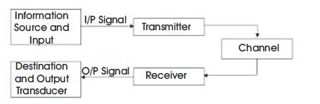
Fiber-optic communication systems are lightwave systems that employ optical fibers for information transmission [3-6]. A typical lightwave communication system is shown in Figure 1 consist of a lightwave transmitter, which is usually a semiconductor laser diode with associated electronics for modulating it with the signals. A transmission channel namely, the optical fiber to carry the modulated light beam and finally, a receiver, which consist of an optical detector and associated electronics for retrieving the signal. The information ie, signal to be transmitted is usually coded into a digital stream of light pulses by modulating the laser diode. These optical pulses then travel through the optical fiber in the form of guided waves and are received by the optical detector from which, the signal is then decoded and retrieved.
Figure 1. Elements of an Optical Network
The optical carrier frequencies are typically ~200 THz, in contrast with the microwave carrier frequencies (~1 GHz). An increase in the information capacity of optical communication systems by a factor up to 10,000 is expected simply because of such high carrier frequencies used for lightwave systems. This increase can be understood by noting that the bandwidth of the modulated carrier can be up to few percent of the carrier frequency. For illustration, 1% as the limiting value, optical communication systems have the potential of carrying information at bit rates ~1 Tb/s. This enormous potential bandwidth of optical communication systems that is the driving force behind the worldwide development and deployment of lightwave systems. Current state-of-the-art systems operate at bit rates ~10 Gb/s, indicating that there is a considerable room for improvement [7-10].
Optical communication systems can be classified into two broad categories. They are guided and unguided.
Modulation format in optical system implies the conversion of electrical signal to optical bit stream. In general, there are two choices for the modulation format of the resulting optical bit stream and are known as the Return-to-Zero (RZ) and Non Return-to-Zero (NRZ) formats as shown in Figure 2.
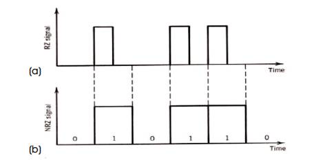
Figure 2. (a) Return-to-Zero (RZ) and (b) NonReturn- to-Zero (NRZ) Formats
Optical fiber is usually used because of its high potential and boundless capabilities. Some of the advantage are listed below,
Since installing an optical fiber cable is both expensive and extremely time consuming, expanding the capacity of an installed network is economically attractive. Thus, a great interest has been established in using Wavelength Division Multiplexing (WDM) Scheme, which offers a very high capacity link. It is a technology of combining a number of wavelength onto the same fiber. A typical WDM system is shown in Figure 3. In WDM system, whole information is transmitted through multiple channels over a single fiber. A key feature of WDM is that the discrete wavelengths that form an orthogonal set of carriers can be separated, routed and switched without interfering with one another. Thus, it is advisory to use the WDM multiplexing technique in optical communication network for high performance [11- 14].
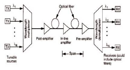
Figure 3. Wavelength Division Multiplexing
Designing WDM links and network requires careful consideration of the system operating conditions. Among these are the link bandwidth, optical power requirements for a specific bit error rate, crosstalk between optical channels, and performance limitations due to non-linear effects. Among all these characteristics, limitations due to non-linear effects are considered in the next section.
If N transmitters operate at bit rates of B1 through BN respectively, then the total bandwidth is B= ΣB1Bi When all the bit rates are equal, then the system capacity is enhanced by a factor N compared to a single-channel link. For example, if the bandwidth of each channel is 2.5 Gbps, then the total bandwidth of the WDM link for eight channels is 20 Gbps, and for 40 channels, it is 100 Gbps [15-16].
At the outputs of the demultiplexer, system parameters that need to be considered include the signal level, noise level, and crosstalk. The Bit Error Rate (BER) of a WDM channel is determined by the optical Signal-to-Noise Ratio (SNR) delivered to the photodetector. For an acceptably low BER in an ideal link, this should be approximately 14 dB measured in a 0.01-nm optical bandwidth. For commercial systems, one typically needs a SNR of 18 to 20 dB. These values then determine the amount of optical power that must be launched into each wavelength channel, the number of EDFAs needed over the desired link length, and the fiber attenuation that can be tolerated in the spans between optical amplifiers [17].
The narrow channel spacing in dense WDM links give rise to crosstalk, which is defined as the feed through of one channel signal into another [18]. Crosstalk can be introduced by almost any component in a WDM system, including optical filters, wavelength multiplexers and demultiplexers, optical switches, optical amplifiers, and the fiber itself. The two types of crosstalk that can occur in WDM systems are intrachannel and interchannel crosstalk. Both of these cause power penalties in the system performance.
As illustrated in Figure 4 for a demultiplexer function, interchannel crosstalk arises when an interfering signal comes from a neighboring channel. This means that the wavelength of the undesired signal is sufficiently far away from the desired signal wavelength, so that the difference is greater than the electrical bandwidth of the receiver.
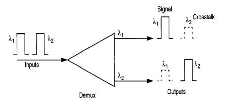
Figure 4. Origin of Interchannel Crosstalk
For intrachannel crosstalk, the interfering signal is at the same wavelength as the desired signal. This effect is more severe than the interchannel crosstalk, since the interference falls within the receiver bandwidth.
When going to the higher multiplexing level of 10 Gbps or more, one starts to encounter effects that can seriously degrade the WDM network performance. Among these effectsare,
The capacity of optical communication system is limited by the ability to mitigate the linear and non-linear distortion caused by the optical channel. In fiber optic communication system, linear impairments are caused by fiber loss, Chromatic Dispersion (CD), and Polarization Mode Dispersion (PMD). Optical power loss due to light propagation inside the fiber results from absorption and scattering and can be easily compensated by the optical amplifiers.
In contrast to linear effect, non-linear effects are very difficult to overcome. When two or more optical fields having different wavelength propagates inside the optical fiber at high data rate, they interact with each other and give rise to a phenomenon called non-linearity. Non-linear effect severely degrades the performance of the WDM system. This effect occur either due to the inelastic scattering phenomenon or intensity dependence of refractive index of the medium. Non-linear classification based on intensity dependence of refractive index of the medium are Self Phase Modulation (SPM), Cross Phase Modulation (CPM) and Four Wave Mixing (FWM) and based on inelastic scattering phenomenon are Simulated Raman Scattering (SRS) and Simulated Brillouin Scattering (SBS).
The Kerr non-linearity gives rise to the Self Phase Modulation (SPM). SPM is observed when an intensity modulated signal is propagated through an optical medium. In SPM, the phase of an optical signal is modulated by itself [28-30]. Figure 5 and Figure 6 show the input and output signal patterns, respectively considering the SPM effect. SPM affects a single light pulse propagating through the medium. Thus, it is seen on a single channel optical fiber communication. It causes a frequency chirp on optical pulse, which causes pulse broadening. SPM caused by group velocity dispersion causes distortions in the waveform that restricts the transmission capacity and the distance over which the signal is propagated. SPM is used for fast optical switching and dispersion managed optical solutions. It has many other applications like chirped-pulse amplification, pulse compression and spectral broadening [31].
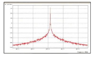
Figure 5. SPM Input Pattern
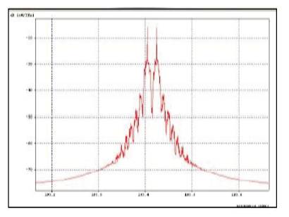
Figure 6. SPM Output Pattern
The most dominating phenomenon in WDM system is Cross Phase Modulation (CPM/XPM). Cross Phase Modulation (XPM) is known as the phenomenon that the variations of intensity of one optical signal can change the refractive index of the fiber (Kerr effects), and modulate the phase of other optical signals co-propagating in the same fiber. The change in phase due to variation in power of adjacent channels strongly affects the system performance [32-36]. XPM leads to inter-channel crosstalk in WDM systems and can produce amplitude and timing jitter. XPM is sometimes used for passive mode locking, ultrafast optical switching, non-linear pulse compression and wavelength compression of WDM channel. Figure 7 and Figure 8 show the input and output signal patterns, respectively considering the XPM effect.
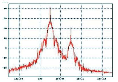
Figure 7. XPM Input Pattern
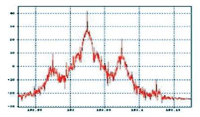
Figure 8. XPM Output Pattern
Four-Wave Mixing (FWM) is a type of optical Kerr effect, and occurs when light of two or more different wavelengths is launched into a fiber. Four wave mixing non-linearity is analogous to third order intermodulation distortion, whereby two or more optical waves at different wavelengths mix to produce new optical waves at other wavelength. Thus, when two signals with frequencies f1 and f2 travel in the fiber, then two new cross products will appear as 2f1 -f2 and 2f2 -f1 [37-40]. The number of interfering products increase rapidly with the number of signals. In FWM phenomenon, when light of distinct wavelength enters into the fiber, it results in the generation of new wave whose wavelength does not match with the parent light. Mixing efficiency is inversely proportional to the fiber dispersion. FWM finds applications in optical phase conjugation, parametric amplification and micro resonator based frequency comb generation. Parametric amplifiers and oscillators based on four-wave mixing use the third order non-linearity, as opposed to most typical parametric oscillators, which use the second-order nonlinearity. It is used in squeezing and wavelength conversion. Figure 9 and Figure 10 show the input and output signal patterns, respectively considering the FWM effect.
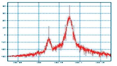
Figure 9. FWM Input Pattern
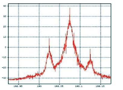
Figure 10. FWM Output Pattern
Stimulated Raman Scattering (SRS) is a phenomenon, where a lower frequency ’signal’ photon induces the inelastic scattering of a higher frequency ’pump’ photon in an optical medium in the non-linear regime as shown in Figure 11. During the propagation of light through a medium, interaction of photons with silica molecules take place. They also interact with themselves and produce scattering effects like Stimulated Raman Scattering in the reverse and forward propagation directions along the fiber resulting in energy distribution in a random direction [41- 42]. In SRS, scattering of energy creates a low wavelength wave called Stoke’s wave, which amplifies higher wavelengths. The basis of Raman amplification is the gain obtained by using such a wave. By lowering the input power, the effect of SRS can be reduced.
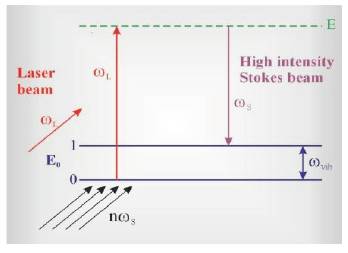
Figure 11. Scheme of SRS
Brillouin scattering is an effect caused by the third order non-linearity of a medium, specifically by that part of the non-linearity, which is related to acoustic photons. Interaction of photons with silica molecules take place during propagation of light. Interaction among themselves produces scattering effects such as SBS in a reverse direction, direction reverse to direction of propagation. In SBS, scattering of energy creates a low wavelength wave called Stoke’s wave, which amplifies higher wavelengths [43-45].
The Brillouin frequency shift depends on the material composition and to some extent the temperature and pressure of the medium. Such dependencies are exploited for fiber optic sensors. Important application of Stimulated Brillouin Scattering is optical phase conjugation.
This paper provides the basic concept of optical fiber network to help people understand why optical fiber technology is attracting a lot of attention for making broadband and other telecommunication services these days. Development of WDM technology proves to be the efficient and cost effective method for upgrading the optical system. But the presence of non-linear effect can adversely affect the communication between two receiving ends. These non-linear effects can be managed through a proper system design. The effects are also useful for many device and system applications like optical switching, soliton formation, wavelength conversion, broadband amplification, de-multiplexing, etc. This work also describes the operating characteristics of optical network using which, an efficient optical system can be implemented.