A Review on Different Resonator based Microwave Filters
Priyanka Srivastava * Arvind Kumar Pandey ** R. K. Chauhan ***
* PG Scholar, Communication Engineering, Madan Mohan Malaviya University of Technology, Gorakhpur, India.
** Research Scholar, Madan Mohan Malaviya University of Technology, Gorakhpur, India.
*** Professor, Department of Electronics and Communication Engineering, Madan Mohan Malaviya University of Technology, Gorakhpur, India.
Abstract
High performance microwave filters have become the need of the modern wireless communication systems. This demands the designing of more compact and efficient microwave filters providing multiple bands. For the miniaturization and integration of the microwave filters, microstrip filters based on multiple mode resonators are of great significance. This paper reviews several multiple band-pass filters based on different multi-mode resonators by focusing on Stepped Impedance Resonator (SIR), Stub Loaded Resonator (SLR) and Ring/Loop Resonator (open and closed) based microwave filters. SIR has size reduction ability and harmonic control with wide tuning range. A SLR has a good stopband rejection ability. It can generate two modes that can efficiently reduce the size of the filters. Loop resonator can be used to reduce the size along with optimized characteristics of filters.
Keywords :
- Multi Mode Resonators,
- Stepped Impedance Resonator (SIR),
- Loop Resonator,
- Ring Resonator,
- Stub Loaded Resonator (SLR),
- Band-pass Filter.
Introduction
Due to the rapid expansion of wireless communication and radio frequency systems like WLAN, Wi-fi, Wi-Max, 3G, 4G etc., good performance microwave filters are required. This leads to a continuous development in designing and manufacturing of more advanced, low cost and compact microwave filters. Also, it demands the multiple communication systems to be designed in the one equipment and thus the multiband band pass microwave filters are required for this growing need. Various multi-mode resonators according to their structure, characteristics and output are used to design different compact and high performance microwave filters. Different shapes and structures of resonators like Stepped Impedance Resonator, open and short circuited stubs resonators, hair-pin resonators, closed ring resonators, open loop resonators, split ring resonators etc. are employed to achieve the desired filter characteristics [1-4]. Realization of dual band, triple band, quadruple band, filters can be done by using resonators. Open or short stubs, by arranging in parallel or series to realize a dual band filter [5-6]. Coupling structures of resonators are employed to achieve dual bands and triple bands from filters. Various dual and tri-band band-pass filters are designed using various length and arrangement of SIRs. Employability of different coupling schemes optimizes the performances as well as compactness of the filters [7- 9]. Multiband filters are designed using open loop and closed loop resonators, which also provide a better rejection performance. [10-11].
The objective of this review paper is to study the three basic types of resonators i.e. Stepped Impedance Resonator (SIR), Loop/Ring Resonator and Stub Loaded Resonator (SLR). The paper is aimed to discuss the characteristics of these resonators by conversing the previous works on these resonators. The paper also confers the effect of these resonators on the performance parameters of various multiband filters.
Section 1 of this paper describes in detail about the Stepped Impedance Resonator based multiband filters. Section 2 gives the designs and description of various loop resonators for the development of band-pass filters. Multiband band-pass filter employing Stub Loaded Resonators are reviewed in Section 3. Final section concludes the review of different methodologies and designs of multiband band-pass filters.
1. Stepped Impedance Resonator
Stepped Impedance Resonators are easier to design and the filters designed using them, utilize comparatively less space than other filters created using stub resonators. They provide a good harmonic control and also wide tuning range based on the position of the varactor. Tuning range can be varied using ratio of the length of low impedance section and that of high-impedance section. But, their electrical performance is limited and they are very good choice for the filters where sharp cutoff is not a necessitate [12].
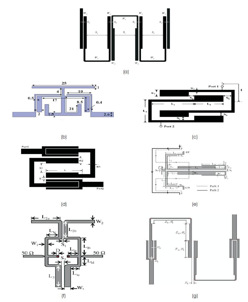
Mitsuo Makimoto and Sadahiko Yamashita in their work [13], proposed the simplest designs for a band pass filter using SIR. These filters have a capability to control spurious response and insertion loss. They used SIR as a transmission line resonator with non-uniform geometry. They took the impedance ratio K as 0.5 for type 1 filter and as 1.5 for type 2 filter. Though, value of K less than one increases the compactness, but it also increases the losses. However, the value of K, when chosen more than one, offers low loss characteristics but increases the size of the filter. A compact three mode SIR as shown in Figure 1 (b) is used by Wei Shen et. al, [14] to develop a microstrip band-pass filter. The compactness is achieved by using a T-shaped open stub and a folded T type open stub at the centre plane. The filter provides sharp skirts and wide stop band characteristics. A new dual band microstrip band-pass filter was designed as shown in Figure 1(a), employing new coupling scheme by Yue Ping Zhang and Mei Sun using SIR [9]. The new coupling scheme when used in interstages, increased the compactness of the layout, while using it at input and output enhances the performances of the bandpass filter. However, to meet the specific bandwidth requirement, it is not so convenient. Using a pseudointerdigital SIR as given in Figure 1(c), Min-Hang Weng et. al, [15] designed a dual band band-pass filter. It featured high isolation between the two bands, compact structure and low insertion loss. A fairly compact dual band band-pass filter was designed by Qing-Xin Chu and Fu-Chang Chen [16], using meandering SIR. The design is shown in Figure 1 (d). It offers better out of band performance. However, in both the filters [15, 16] the coupling coefficients of two pass bands and both the resonant frequencies of the SIRs are dependent therefore, controlling the bandwidth of each passband independently is not possible. Chung-I G. Hsu et. al, [17] proposed a tri band band-pass filter shown in Figure 1(e) using a tri-section SIR in is work. Though having a complex structure, the filter affords sharp passband skirts. Ching-Her Lee et. al, [18] in their paper, proposed a versatile method of combining two quarter wavelength SIRs into one having a common shorting end. Each SIR in the structure given in Figure 1(f) controls one or two pass-bands. A novel tunable triple-band band-pass filter is designed by Xue Ming Lin and Qing Xin Chu [19] using a tri section SIR. The structure is shown in Figure 1(g). The hairpin structure reduced the size of the filter and the usage of the new coupling scheme at the input and output improved the performance. The designs [18, 19] though being flexible cannot be extended to higher orders.
2. Loop and Ring Resonator
This category contains circular ring resonator, square loop resonator etc. under which there is further bifurcation of open loop and closed loop resonator. For designing the cross coupled resonator filters, the loop resonator exhibits flexibility. It is also renowned for compact designing of microwave filters.
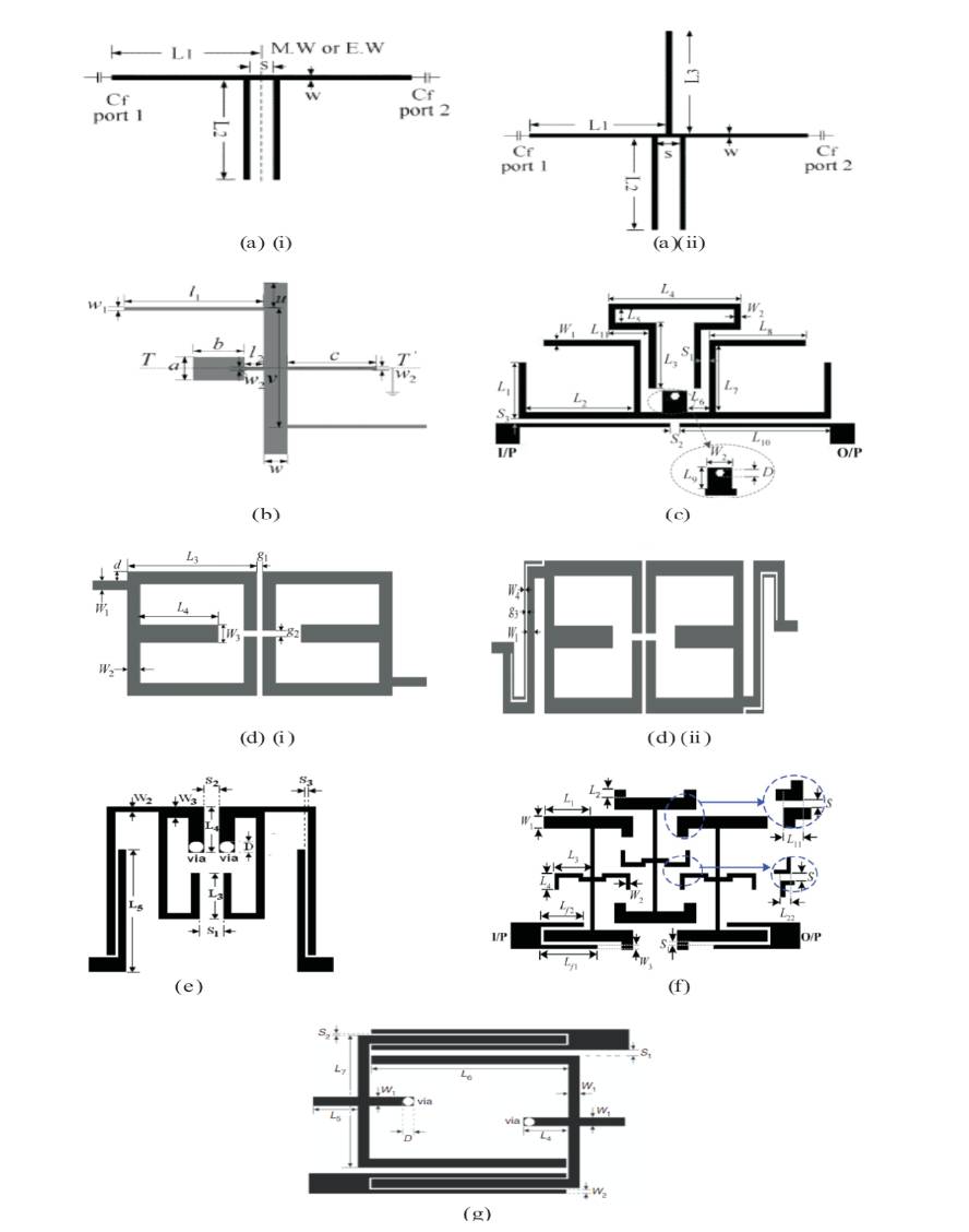
Wen-Hua Tu in his work [20], proposed two broadband microstrip band-pass filters using a triple mode loaded open loop resonator. The triple mode resonator consists of a loaded open loop and a half wave resonator as shown in Figure 2 (a). A very sharp cut-off response is attained by the filter. P. Mondal and M. Mandal proposed a design as shown in Figure 2 (b) with external coupling achieved by varying the dimension and position of the stub loaded resonator [10]. The filter designed is compact in size and also provides a good out of band rejection. A detailed discussion on dual mode open loop resonators and filters is done by Jia-Sheng Hong et al. in their paper [21]. In open loop resonator, the two modes are not coupled to each other unlike square loop resonator even if the modes are split. The filter shows an asymmetric response with simple design as shown in Figure 2 (c). The structure is compact but increases the size of the filter for higher orders. Michiaki Matsuo et al. [22], in their work presented a dual mode stepped impedance ring resonator. The two ports in the ring 0 resonator structure are spatially separated at 90 of electrical length. A perturbation is loaded at the symmetric plane which is providing an impedance step. The filter structures proposed in their work possess excellent attenuation characteristics as well as low radiation property. Due to the one wavelength resonator structure, the filter has a compact size. A band-pass filter designed using periodic stepped impedance ring resonator as shown in Figure 2 (d) (i) to (iv) is proposed in [23] by Jen-Tsai Kuo and Chih-Yuan Tsai. The periodicity for stepped behavior is obtained by varying N= 1 to 4. The filter provides optimal reduction in area. Also due to the use of periodic structure, the filter holds improved upper stopband performance. Mohd Khairul Mohd Salleh et al. [24] projected a dual mode ring resonator which is fed by two quarter wavelength side coupled lines. The structure of resonator as shown in Figure 2 (e) allows to fix the central frequency, bandwidth, insertion loss and transmission zero frequencies. The designed filter is compact in nature and offers a very high out-of-band rejection levels as well. A compact low loss and high selectivity filter is designed by J. W. Fan et al. [11] using a loaded open loop resonator with multi band characteristics. The resonator is used to design dual band and triple band filters as shown in Figures 2 (i) (i) and 2 (i) (ii) respectively. A compact size dual-band filter, as shown in Figure 2 (f) is designed by Sha Luo and Lei Zhu [25]. They employed uniform and periodical stub loaded configurations in dual mode ring resonator. It provides adjustable spacing between the two pass-bands. S. Luo et al. [26] presented a single stub loaded slot ring resonator with tunable frequency bands as given in Figure 2 (h). The resonator is dual mode, and dual band. The strength and nature of the external coupling is determined by the microstrip open circuited stub's characteristics which controls the ratio of the center frequency of the two operating pass-bands. J.Z. Chen et al. [27] and M.T. Doan et al. [28] used Square Ring Stub Loaded Resonators (SRSLR) to design tri band microwave filters that posses simple structure, fairly good compactness, high selectivity and good tuning ability. The structure proposed in [28] is shown in Figure 2 (g).
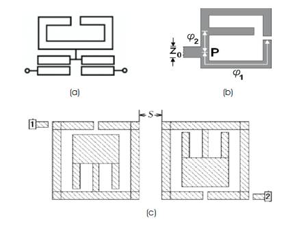
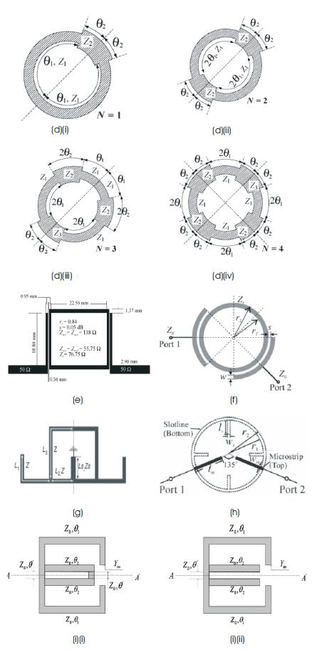
Figure 2. Structures of Loop or Ring Resonators and Filters: (a) A Three Pole Band-Pass Filter [20], (b) An SLR with Tapped-Line Feeding [10], (c) Coupled Dual Mode Open Loop Resonators [21] (d) Periodic Ring Resonator with (i) N=1 (ii) N=2 (iii) N=3 and (iv) N=4 [23], (e) A Side Coupled Ring Resonator [24], (f) A Dual Band BPF Using Ring Resonator [25], (g) A Square Ring SLR [28], (h) A Dual Mode Slot Ring Resonator [26], (i) (i) A Dual- Band Resonator [11], (i) (ii) A Tri-band Resonator [11]
3. Stub Loaded Resonator
A stub is an open circuited or close circuited length of a transmission line. It can be connected in series or parallel with the feed line. For microstrip line structures, shunt stubs are preferred while series stubs are preferred for slot line or coplanar waveguide [12]. Stub tuning circuit is suitable for the reason that they can be fabricated as a part of the transmission line.
Songbai Zhang and Lei Zhu presented a compact and highly selective microstrip BPF by using a triple and quad mode stub-loaded resonator [29]. Though the filters fabricated have sharp roll-off skirts, still better selectivity can be achieved by increasing the transmission zeros. The structures of the triple mode and quad mode resonators are shown in Figures 3 (a) (i) and (a) (ii) respectively. Hongwei Deng et al. [30] designed a new stub loaded resonator having quintuple modes as given in Figure 3 (b). This ultrawide band BPF provides sharp rejection skirts near the cutoff frequencies. Out of three even mode and two odd mode resonance frequencies, the even mode frequencies can be flexibly controlled. Due to the use of long, straight stubs the filter size is considerable. Various dual band resonators with small size are also used to design dual band band–pass filters. Stub loaded multiple mode resonators is used by F.C. Chen et al. [31] to design a dual band compact sized band-pass filter. Figure 3 (c) shows the structure of the filter. The filter possesses controllable bandwidth and high out-of-band attenuation. However, insertion loss is comparatively more as compared to other contemporary dual band filters. Xiu Yin Zhang et al. [32] designed a dual band BPF using stub loaded resonator which can be implemented with three transmission zeros. By introducing spur line, four transmission zeros is generated that improves the selectivity of the filter. Both the structures are given in Figures 3 (d) (i) and d (ii). Using a pseudointerdigital short stub loaded resonator and a meandering short stub loaded resonator, the performance of the filter is improved and the size is reduced. Fu-Chang Chen et al. [33] proposed two designs of a dual band BPF. One of the designs is shown in Figure 3 (e). The design using pseudo interdigital SSLR provides compact size and generation of transmission zeros and meandering SSLR offers independently controllable bandwidths. Fu-Chang Chen and Qing-Xin Chu [34] presented a stub loaded resonator with multiple stubs which is used to design a dual band BPF. The structure of the band-pass filter is shown in Figure 3 (f). The bandwidth of the second band of the filter is conveniently controllable by adjusting the centre stubs coupling. Though higher order filters can easily be designed using this resonator, but the structure is complex for lower order filters. A tri-band BPF is designed by F. C. Chen et al. [35] using a short and open circuited stub loaded resonator. The layout of the filter is shown in Figure 3(g). The second band of the designed filter is fixed while first and third pass bands can be adjusted by varying the length of the stubs. It has improved selectivity and fairly good out-of band rejection characteristics.
There are several multi band band-pass filters that can be designed by employing a ring resonator with an open circuited stub, a stepped impedance resonator with a stub or a ring resonator with an SIR [36-38, 14]. The employment of these combinations bestows the scope of immense improvement in the characteristics of the microwave filters as well as reduction in size of the filters. High selectivity, multiple bands with high out-of-band rejection, low losses. In Figure 3, structures of stub loaded resonators and filters are given. Figure 3 (a) (i) A triple mode SLR [29], (a) (ii) A quad mode SLR [29], (b) A quintuple mode SLR [30], (c) Layout of a dual band BPF [31], (d) (i) A filter with three transmission zeros [32], (d) (ii) A filter with four transmission zeros [32], (e) A dual band BPF [33], (f) A third order dual band filter [34], (g) Layout of tri-band filter [35] etc. are some of the features that can be achieved by these structures which bring revolution in the field of microwave filter designing.
Conclusion
This paper reviewed various single, dual and triple band BPFs using three types of structures i.e. Stepped Impedance Resonators (SIR), ring and loop resonators and Stub Loaded Resonators (SLR). SIR structures are valuable for size reduction as well as for tunable bands. Ring resonators and open or closed loop resonators are also favorable for compact size. They also have good electrical performance. Stub loaded resonators brings simplicity in structures and can provide flexibility in tuning of the multiple pass-bands as per desired range.
References
[1]. Nguyen C. and Chang K, (1985). “Analysis and design of spurline bandstop filters,” IEEE MTT-S Digest, Vol.33, No .12, pp.1416-1421.
[2]. Tu W. H. and Chang K, (2005). “Compact microstrip bandstop filter using open stub and spurline,” IEEE Microwave Wireless Components Lett., Vol. 15,No.4, pp. 268-270.
[3]. Chen Wu. N., Weng M. H., Tang I. T., Hung C. Y., Cheng T. C. and Houng M P., (2004). “Notch Filters with Novel Microstrip Triangle Type Resonator", IEEE Transactions on Ultrasonics, Ferroelectrics, and Frequency Control, Vol. 51, No.8, pp.1018-1021.
[4]. Garcia – Garcia J., Bonache J., Gil I., Martin F., Marques R., Falcone F., Lopetegi T., Laso M. A. G. and Sorolla M., (2005). “Comparison of electromagnetic band gap and split ring resonator microstrip lines as stop band structures,” Microwave Opt Technol Lett., Vol. 44, pp. 376-379.
[5]. C. Quendo, E. Rius, and C. Person, (2003). “An original topology of dual-band filter with transmission zeros,” in IEEE MTT-S Int. Microw. Symp. Dig. Vol. 2, pp. 1093-1096.
[6]. C. M. Tsai, H. M. Lee, and C. C. Tsai, (2005). “Planar filter design with fully controllable second passband,” IEEE Trans. Microw. Theory Tech., Vol. 53, No. 11, pp. 3429-3439.
[7]. J. T. Kuo and E. Shih, (2003). “Microstrip steppedimpedance resonator band-pass filter with an extended optimal rejection bandwidth,” IEEE Trans. Microw. Theory Tech. Vol. 51, No.5, pp. 1554-1559.
[8]. S. Sun and L. Zhu, (2005). “Coupling dispersions of parallel coupled microstrip lines for dual-band filters with controllable fractional pass bandwidths,” in IEEE MTT-S Int. Microw. Symp. Dig.
[9]. Y. P. Zhang and M. Sun, (2006). “Dual-band microstrip bandpass filter using stepped-impedance resonators with new coupling schemes,” IEEE Trans. Microw. Theory Tech., Vol. 54, No. 10, pp. 3779-3785.
[10]. P. Mondal and M. Mandal, (2008). “ Design of dualband bandpass filters using stub-loaded open loop resonators,” IEEE Trans. Microw. Theory Tech., Vol. 56, No. 1, pp. 150-155.
[11]. J. W. Fan, C. H. Liang, and Y. J. Wu, (2007). “Compact dual-band and tri-band filters with loaded open-loop resonators”, J. Electromagn. Waves Appl., Vol. 21, No. 15, pp. 2371-2378.
[12]. D. M. Pozar, (1998). Microwave Engineering, 2nd ed. New York :Wiley.
[13]. M. Makimoto, S.Yamashita,(1980). “Bandpass filters using parallel coupled stripline stepped impedance resonators,” IEEE Trans. Microw. Theory Tech., Vol. 28, No. 12, pp. 1413–1417.
[14]. W. Shen, X. W. Sun, and W. Y. Yin, (2009). “A novel microstrip filter using three-mode stepped impedance resonator (TSIR),” IEEE Microw.Wireless Compon. Lett., Vol. 19, No. 12, pp. 774–776.
[15]. Weng, M.H., Wu, H.W., Su, Y.K. (2007). “Compact and low lossdual-band bandpass filter using pseudo-interdigital stepped impedance resonators for WLANs”, IEEE Microw. Wirel. Compon. Lett., Vol. 17,No.3, pp. 187–189.
[16]. Chu, Q.X., Chen, F.C. (2008). “A compact dual-band bandpass filter using meandering stepped impedance resonators”, IEEE Microw. Wirel. Compon. Lett., Vol. 18,No. 5, pp. 320–322.
[17]. C. I. G. Hsu, C. H. Lee, and Y. H. Hsieh, (2008). “Tri-band bandpass filter with sharp passband skirts designed using trisection SIRs”, IEEE Microw. Wireless Compon. Lett.,Vol. 18, No. 1, pp. 19–21.
[18] . C. H. Lee, C. I. G. Hsu, and H. K. Jhuang, (2006). “Design of a new tri-band microstrip BPF using combined quarter-wavelength SIRs,” IEEE Microw. Wireless Compon. Lett., Vol. 16, No. 11, pp. 594–596.
[19] . X. M. Lin and Q. X. Chu, (2007)“Design of triple-band bandpass filter using tri-section stepped-impedance resonators,” in Proc. Int. Microw. Millimeter Wave Tech. Conf., Guilin, China, pp. 1–3.
[20]. W.-H. Tu, (2010). “Sharp-rejection broadband microstrip bandpass filters using loaded open-loop resonator,” IEEE MTT-S Int. Microw. Symp. Dig., pp. 1696–1699.
[21] . J. S. Hong, H. Shaman, and Y. H. Chun, (2007). “Dualmode microstrip openloop resonators and filters,” IEEE Trans. Microw. Theory Tech., Vol. 55, No. 8, pp. 1764–1770.
[22] . M. Matsuo, H. Yabuki, and M. Makimoto, (2001). “Dual-mode stepped impedance ring resonator for bandpass filter applications,” IEEE Trans. Microw. Theory Tech., Vol. 49,No. 7, pp. 1235–1240.
[23]. J.-T. Kuo and C.-Y. Tsai, (2006). “Periodic steppedimpedance ring resonator (PSIRR) bandpass filter with a miniaturized area and desirable upper stipband charateristics”, IEEE Trans. Microw. Theory Tech., Vol. 54, No. 3, pp. 1107–1112.
[24] . M. K. M. Salleh, G. Prigent, O. Pigaglio, and R. Crampagne, (2008). “Quarter-wavelength side-coupled ring resonator for bandpass filters,” IEEE Trans. Microw. Theory Tech.,Vol. 56, No. 1, pp. 156–162.
[25]. Luo, S., Zhu, L. (2009). “A novel dual-mode dual-band bandpass filter based on a single ring resonator”, IEEE Microw. Wirel. Compon. Lett, Vol.19,No.8, pp. 497–499.
[26]. Luo, S., Zhu, L., Sun, S. (2009). “A dual- mode dualband bandpass filter using a single ring resonator”, Proc. Asia-PacificMicrow. Conf., pp. 921–924.
[27] . J. Z. Chen, N. Wang, Y. He, and C. H. Liang, (2011). “Fourth-order tri-band bandpass filter using square ring loaded resonators,” Electron. Lett., Vol. 47, No. 15, pp. 858–859.
[28]. M. T. Doan, W.Q.Che, and W. J. Feng, (2012). “Tri-band bandpass filter using square ring short stub loaded resonators,” Electron. Lett., Vol. 48, No. 2, pp. 106–107.
[29]. S. B. Zhang and L. Zhu, (2011). “Compact and highselectivity microstrip bandpass filters using triple-/quadmode stub-loaded resonators,” IEEE Microw. Wireless Compon. Lett., Vol. 21, No. 10, pp. 522–524.
[30]. H. W. Deng, Y. J. Zhao, L. Zhang, X. S. Zhang, and S. P. Gao, (2010). “Compact quintuple-mode stub-loaded resonator and UWB filter,” IEEE Microw. Wireless Compon. Lett.,Vol. 20,No. 8, pp. 438–440.
[31] F. C. Chen, Q. X. Chu, Z. H. Li, and X. H. Wu, (2012). “Compact dual-band bandpass filter with controllable bandwidths using stub-loaded multiple- mode resonator”, IET Microw. Antennas. Propag, Vol. 6, No. 10, pp. 1172–1178.
[32]. X. Y. Zhang, J.-X. Chen, Q. Xue and S.-M. Li, (2007). “Dual-band bandpass filters using stub-loaded resonators,” IEEE Microw. Wireless Compon. Lett., Vol.17. No.8, pp.583- 585.
[33]. Chen, F.C., Chu, Q.X., Tu, Z.H., (2009). “Design of compact dual-band bandpass filter using short stub loaded resonator”, Microw. Opt. Technol. Lett., Vol.51, No.4, pp. 959–963.
[34]. Chen, F.C., Chu, Q.X., (2010). “Novel multistub loaded resonator and its application to high-order dual-band filters”, IEEE Trans. Microw. Theory Tech., Vol.58, No.6, pp. 1551–1556.
[35]. F. C. Chen, Q. X. Chu, and Z. H. Tu, (2008). “Tri-band bandpass filter using stub loaded resonators,” Electron. Lett., Vol. 44, pp. 747–749.
[36]. R. Li and L. Zhu, (2007). “Compact UWB bandpass filter using stub loaded multiple-mode resonator,” IEEE Microw. Wireless Comp. Letts., Vol. 17, No. 1, pp. 40–42.
[37]. Q. X. Chu and X. K. Tian, (2010). “Design of UWB bandpass filter using stepped-impedance stub-loaded resonator,” IEEE Microw. Wireless Compon. Lett., Vol. 20, No. 9, pp. 501–503.
[38]. Gorur, A., Karpuz, C., (2007). “Compact dual-band bandpass filters using dual mode resonators”, IEEE MTT-S Int. Microw. Symp. Dig., pp. 905–908.