
Figure1. Diagram of a Meander Line Section
A multi band meander line antenna is proposed in this paper for ISM and Ultra Wide-Band (UWB) applications. The size of the antenna is 60x40x1.6 mm3. FR4 Epoxy having dielectric constant of 4.4 and dielectric loss tangent of 0.02 is taken as substrate of the antenna. Co-axial probe feed and capacitive feed is used to excite the antenna. Dual feeding is used in order to enhance the operating bandwidth and radiation efficiency of the proposed antenna. The experimental 10 dB bandwidth of 800 MHz, 2.42 GHz and 1.5 GHz can be obtained at various resonant frequencies while simulating the design on HFSS 13.0. The proposed antenna can be used for various applications including mobile phone communication and Ultra-wide Band (UWB) applications and also WLAN application at 5GHz.
Microstrip patch antenna has emerged as highly potential in antennas advancement and research in recent years. Microstrip patch antennas may be of any shape depending upon the enhancement of its parameters and feasibility, for industrial and scientific applications. Some of the shapes includes rectangular, circular, elliptical etc. Meandered line antennas are also a part of microstrip patch antennas which is shown in Figure 1.
Figure1. Diagram of a Meander Line Section
Multiple frequency bands can be obtained by using meander lines as patch for microstrip patch antenna but the major disadvantage of such antennas are its narrow bandwidth, which restricts its maximum data transfer ability.
Multiple meander slots can be introduced in the radiating patch that can be used as receiving antenna in energy harvesting system[1]. A meander line antenna can be printed on USB-WLAN card with notebook PC-Housing for WLAN applications[2]. Also, it can be used in biomedical applications and can operate in Zigbee dual band 868- 928 MHz and 2.4-2.5 GHz [3]. Meander line antenna can be used as wearable antenna[4] using textile fabric material as dielectric substrate, which may include jeans cotton, polycot, polyester, shieldit etc. The gain and radiation efficiency of the meander line antenna can be increased by using a capacitive feed structure[5], its applications includes LTE Communication[6] and Personal Wireless Communication Systems[7]. Bandwidth and efficiency enhancement with low cross polarization and high isolation can be achieved by using dual feed technique[8-11].
In this paper, the authors describe a multi-band, dual-feed meander line antenna which can be used for ISM and UWB applications. The co-axial probe feed and capacitive feed have been provided to the copper patch through ground plane. The position of the probe feed is chosen such that the input impedance of the antenna matches with the 50 ohm characteristic impedance of the co-axial probe feed.
The geometry of the proposed microstrip patch antenna is shown in Figure 2. It consist of meander lines, co-axial probe and capacitive feed. The height of the substrate is 1.6 mm. The radiating patch is made of copper which consist of meander lines, horizontal line dimensions are 36 x 4 mm2 and vertical line dimensions are 4 x 4 mm2. The thickness of the patch is 0.035 mm. FR4 epoxy, of relative permittivity 4.4 and loss tangent is 0.02 is used as a dielectric substrate, dimensions of which is 40 X 60 X 1.6 mm3. Co-axial probe feeding and capacitive feeding using lumped port is used to excite the antenna. The position of the co-axial probe feeding is x=8 mm, y=1 mm with respect to origin as shown in Figure 2. Detailed dimensions of the proposed antenna is shown in Figure 3 and Table 1.
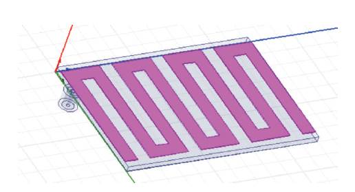
Figure 2. Actual HFSS Model
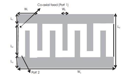
Figure 3. Dimensions of Slotted Patch
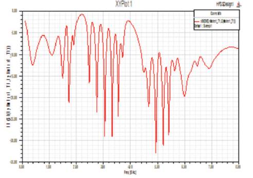
Figure 4. Return Loss of Proposed Antenna
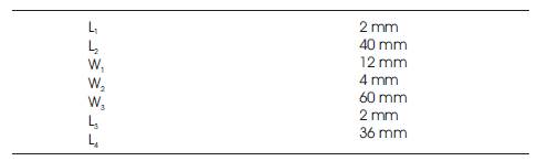
Table 1. Dimensions of Designed Antenna
Simulation of the proposed antenna has been done on HFSS 13.0 tool which works on finite element method (FEM) solver for electromagnetic structures and is used in antenna designing and complex RF electronic circuit designing like filters and transmission lines. The various results obtained after the simulation are shown below:
Simulating result of return loss is shown in Figure 4 and Table 2.
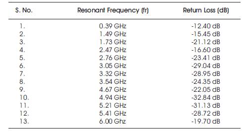
Table.2. Frequency vs. Return Loss Table
Thirteen resonant frequencies at 0.39 GHz, 1.49 GHz, 1.73 GHz, 2.47 GHz, 2.76 GHz, 3.05 GHz, 3.32 GHz, 3.54 GHz, 4.67 GHz, 4.94 GHz, 5.21 GHz, 5.41 GHz and 6 GHz which have respective return loss of -12.40 dB, -15.45 dB, -21.12 dB, -16.60 dB, -23.41 dB, -29.04 dB, -28.95 dB, -24.35 dB, - 22.05 dB, -32.84 dB, -31.13 dB, -28.72 dB and -19.7 dB. Also, we can obtain 10 dB bandwidth of 60 MHz at 2.47 GHz and 2.84 GHz at various resonant frequencies. Minimum return loss of -32.84 dB is obtained at 4.94 GHz and maximum return loss of -12.4 dB is obtained at 0.39 GHz.
For a practically feasible antenna, its voltage standing wave ratio should be more than 1 and less than 2 i.e. 1 < VSWR < 2. Figure 5 shows the simulated VSWR and the numerical data has been shown in Table 3. Simulation results shows VSWR of 1.58, 1.36, 1.19, 1.94, 1.83, 1.92, 2.13, 2.55, 2.31, 2.12, 2.25, 2.45 and 1.41 at 0.39 GHz, 1.49 GHz, 1.73 GHz, 2.47 GHZ, 2.76 GHZ, 3.05 GHZ, 3.32 GHZ, 3.54 GHZ, 4.67 GHZ, 4.94 GHZ, 5.21 GHZ, 5.41 GHZ and 6 GHZ respectively.
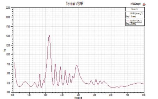
Figure 5. VSWR of Proposed Antenna
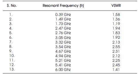
Table 3. VSWR
A radiation pattern is defined as a mathematical function or a graphical representation of the radiation properties of an antenna as a function of space coordinates.
It is clear from Figure 6 and Table 4, that the maximum gain of 3.4 dB can be obtained at 2.5 GHz frequency having theta = 60° and Phi = 120°. Also, the radiation pattern of proposed antenna is bi-directional in the end–fire side of propagation.
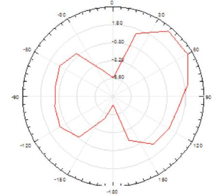
Figure 6. Radiation Pattern at 2.5 Ghz
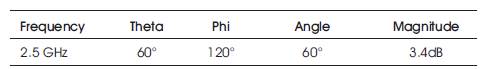
Table 4. Radiation Pattern
3D polar plot represents the amount of radiation absorbed by the radiation box of microstrip patch antenna. The 3D polar plot of proposed antenna is shown in Figure 7.
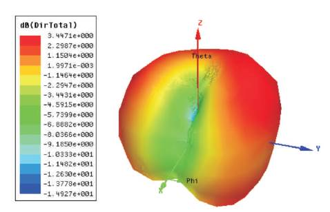
Figure 7. 3D Radiation Polar Plot of Proposed Antenna
The 3D current distribution plot gives the relationship between the co-polarization and cross-polarization components. The current distribution polar plot is shown in Figure 8.
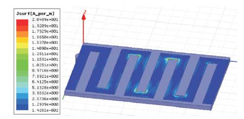
Figure 8. Current Distribution of Proposed Antenna
Various electric field intensities are obtained throughout the patch as shown in Figure 9. Maximum intensities will be obtained at the edges of the patch due to charge accumulation.
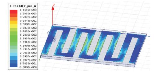
Figure 9. Electric Field Distribution of Proposed Antenna
A broadband meander line antenna having dual-feed has been presented in this paper. Simulated results of the proposed antenna have been discussed. Enhanced impedance bandwidth and radiation efficiency were obtained by using dual feeding mechanism as compared to single probe feeding. Also, it can be used to operate at 2.45 GHz ISM band for various applications like Bluetooth communication, Wi-Max, dual band WLAN application at 2.5 GHz and 5 GHz and at UWB frequencies applications in medical monitoring, imaging and military applications.
Thus, wide areas of possible applications are available for the presented antenna.