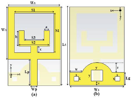
Figure 1. (a) Front View (radiating Element) (b) Back View (defected Ground Plane).
A compact microstrip patch antenna with defected ground structure for WiMAX and WLAN applications is proposed in this paper. The substrate used for this antenna is ROGER 3003 with dimensions 36 x 24mm2 . The front side of the antenna consists of the square shape strip enclosing a U shape strip, which is connected to the square through a small strip. The ground i.e. on the back side of the substrate, having curved shape, three square shaped polygons are etched through, that will provide the defected ground plane. The main outer square is fed by a microstrip feed line having 50Ω impedance. The defected ground structure will provide better impedance matching. This proposed antenna has large bandwidth (0.33 GHz (2.20-2.53 GHz), 1.15 GHz (3.09-4.24 GHz) and 0.86 GHz (5.03-5.89 GHz)), high gain (2.81 dBi (2.20- 2.53 GHz), 2.65 dBi (3.09-4.24 GHz) and 4.38 dBi (5.03-5.89 GHz)) and good antenna total efficiency.
In the recent years, there is great progress in the microstrip patch antenna designs [1]. Now the goal of designing the microstrip patch antenna are those that have features like low cost, light weight, compact and operates in multiband frequency range[2]. UWB microstrip patch antennas are the antennas that cover a wide range of frequency band. Presently, there is huge requirement of the antennas that can operate for different wireless applications at different frequency bands. Particularly, for the antenna to become multi-function at the multi-service antenna technology is the very essential part of the succeeding generations of communication systems. The next generation networks require that the antenna size should be as small as possible and data rate should be high. The demand of portable antenna technology has grown very much with the increasing demand of antenna for the cellular and mobile technologies.
Now there is a requirement that the microstrip patch antenna should work on different wireless frequency bands with great radiation efficiency, improved radiation pattern and high gain without increasing the antenna dimensions. This is possible by designing the microstrip patch antenna with defected ground structure (DGS) [2]. The microstrip patch antenna with defected ground plane is obtained by etching a defect from the ground plane that may be of any geometry e.g. dumbbell- shaped, circular, spiral shaped, rectangular, square, fractal, half-circle, V-shaped etc. [3] The shape of defect can be selected from these different shapes as per required application and required frequency band of operation. A DGS may be located below the microstrip feed line and it will disturb the electromagnetic field nearby the defect. This confined surface current gives escalation to the inductive effect (L) and the confined electric field gives excitation to the capacitive effect (C). This in result gives rise to the changes in the resonant characteristics of the antenna due to the DGS [3].
Now, there is a challenge to design the multi-band antenna for several wireless applications incorporated on a single antenna. DGS helps in implementing the microstrip patch antenna with improved design, reduced size and also provides cross polarization suppression when it is used on the different operating bands [4, 5].
The traditional microstrip patch antennas with defected ground structure were using the FR4 substrate for analysis, simulation as well as fabrication. In proposed antenna ROGER 3003 is used as substrate to achieve better results.
In this paper, authors have designed a tri-band antenna for the WiMAX and WLAN applications. According to IEEE standards, WiMAX works on the 3.5/5.5 GHz band and WLAN works on the 2.4/2.5/5.2/5.8 GHz band [12]. To cover all these frequency bands, a tri-band antenna is designed. Firstly we have to study some dual band antenna configurations then we carry on further for some more multi-band antennas.
Some dual band antennas have been discussed in [6-8] . A coplanar waveguide dual wide band antenna was discussed in [6]. It consists of U shape mono pole and triangular monopole, showing the dual band characteristics that covers the WLAN frequency bands [6] . Another very compact dual band patch antenna has been discussed in [7]. In this, the antenna patch consists of concentric double split rings. For the upper band tuning, there addition of tuning arms to the microstrip feed line carried out, which helps in tuning [7]. Some triple band antenna designs have been reported in [9-13] . A unidirectional triple band antenna is presented in the [9], for WiMAX/WLAN applications. It has five dipoles for having different functioning for different frequency bands. This 2 design had limitation of very large size i.e. 100 x 60 mm [9]. Another tri-band antenna was discussed in which three operating bands were attained by widespread rectangular slot with the insertion of T-shaped strip into it [10] . The bandwidth enhancement was obtained by introducing a staircase pattern into the wide rectangular slot. Another printed monopole antenna was presented for triband applications with asymmetric coplanar strip fed (ACS), that was carried out by the open-ended slots for its working [11]. It mentions a band excluded function by taking the metal strips of proper dimensions. A CPW-fed planer triple band mono pole antenna for WiMAX and WLAN applications was discussed in [12]. It consists of very simple radiating patch having two bent slots. It has the property of band rejection that provides enhanced performance [12]. Another multifrequency antenna has been reported in [13], which consists of small circular ring shaped strips with curved shape defected ground structure, having defect of isosceles triangle shape. This antenna has small gain and less efficiency as we move from lower frequency band to higher frequency band.
In this paper, microstrip patch antenna using DGS is proposed. The antenna consists of a U-shape metal strip enclosed inside a square shape metal strip and having the curved defected ground plane with three square polygons of different area etched; those act as the defects in the ground plane that will provide the better impedance matching. All the parameters of this proposed antenna are optimized and analysed with the aid of CST Microwave Studio Suite. The simulated results of the proposed antenna show that it can radiate three frequency resonant modes, that covers all the three frequency bands required for the WiMAX/WLAN applications.
The traditional antennas are analysed, simulated and fabricated using the FR4 substrate, but the proposed antenna is simulated using ROGER 3003 due to following advantages:
The configuration of the suggested tri band antenna is shown in Figure 1. The antenna is printed on the ROGER 3003 substrate of area 36 x 24 mm2 having thickness of 1.52 mm, with a relative permittivity (εr) of 3 and having a tangent loss (δ) of 0.0013. The antenna substrate with low relative permittivity and more thickness provides good efficiency, antenna performance and larger bandwidth [1].
The main radiating patch is printed on the front side of the substrate, it comprises the square metal strip shape patch surrounding a U-shape metal strip. The square metal strip and the U-shape strip are connected through the strip 'c'. The length of the strip 'c' controls the mutual coupling between the square shape and U-shape metal strip. The length of the strip 'c' is chosen where the various optimized results of the antenna are obtained. The main outer square strip is fed by the microstrip feed line for the antenna excitation as shown in Figure 1.
The partial ground plane i.e. printed on the back side of the substrate comprises a curved shape. In addition to the curved shape, three square shape polygons have been also etched as defect in the ground plane as shown in Figure 1. This defectiveness in the ground plane makes the antenna with defected ground structure. These defects are below the microstrip feed line that will change its characteristics and provide the good impedance matching with the improved bandwidth. The curved shape of defected ground plane and main radiating patch provides the three frequency bands required for the operation of the antenna for the WiMAX and WLAN applications.
Figure 1. (a) Front View (radiating Element) (b) Back View (defected Ground Plane).
The three frequency bands obtained from the simulation of the proposed antenna using CST Studio Suite are shown in Figure 2. These are (2.20-2.53) GHz, (3.09-4.24) GHz and (5.03-5.89) GHz respectively.
The proposed antenna with front view (radiating element) and the back view (defected ground plane) is shown in Figure 1. The various dimensions of the antenna are mentioned in Table 1. All the values (sizes) of the parameters mentioned in Table 1 are measured in mm units of length.

Table 1. Values of Different Parameters of the Proposed Antenna
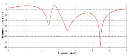
Figure 2. Simulated Return Loss of the Presented Antenna
The simulated result i.e. return loss of the proposed antenna is shown in Figure 2. It is obtained from this plot that the peak return loss of antenna in three frequency bands are -19.33 dB at 2.4 GHz, -24.25 dB at 3.5 GHz and -39.5 dB at 5.5 GHz. The bandwidth obtained is 0.33 GHz (2.20-2.53 GHz), 1.15 GHz (3.09-4.24 GHz) and 0.86 GHz (5.03-5.89 GHz) respectively.
The simulated result of total efficiency (linear) of the proposed antenna is shown in Figure 3. The total efficiencies shown by the proposed antenna are 95.16% at 2.45 GHz, 91.94% at 3.5 GHz, 76.84% at 5.2 GHz, 77% at 5.5 GHz and 71.47 % at 5.8 GHz. These efficiency values of proposed antenna are good for making the antenna practicable for the WiMAX/ WLAN applications.
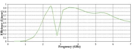
Figure 3. Simulated Total Efficiency (linear) of Proposed Antenna
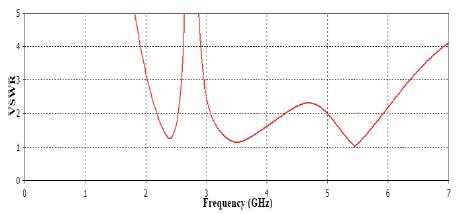
Figure 4. Simulated VSWR Vs Frequency Plot of Proposed Antenna
The Voltage Standing Wave Ratio (VSWR) is also an important part of the antenna performance. When there is mismatch of the load with the feed line, then the standing waves are generated by the combination of the transmitted waves and the reflected waves. Ideally the value of VSWR should remain in the range of 1and 2. As shown in Figure 4. VSWR of the proposed antenna in all three bands lies in between the range of 1 and 2. It is good for practical applications.
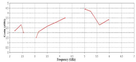
Figure 5. Gain (dBi) Vs Frequency Plot of Simulated Proposed Antenna
The antenna proposed through this approach has high gain as shown in Figure 5. The peak gains obtained through the simulation in three bands are 2.81 dBi (2.20-2.53 GHz), 2.65 dBi (3.09-4.24 GHz) and 4.38 dBi (5.03-5.89 GHz) respectively. Obtained gain is good for the WiMAX and WLAN applications.
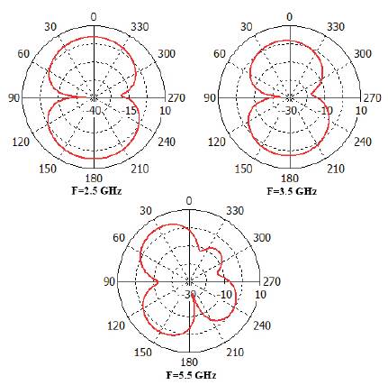
Figure 6. Simulated E-plane Radiation Pattern at Different Frequencies of WiMAX/WLAN
The E-plane (yz-plane) radiation pattern of proposed antenna is shown in Figure 6. It is illustrated from the figure that the antenna has good radiation pattern at frequencies 2.5 GHz and 3.5 GHz, having shape of the mathematical digit '8'. It has some distortion at higher frequencies as shown in Figure 6 at 5.5 GHz, because at high frequencies there is generation of ripples giving rise to directional pattern instead of omni-directional.

Figure 7. Simulated H-plane Radiation Pattern at Different Frequencies of WiMAX/WLAN
The H-plane (xz-plane) radiation pattern of the proposed antenna is shown in Figure 7. From this pattern, it is illustrated the antenna has circular shape pattern showing the omnidirectional pattern at all the three frequencies i.e. 2.5 GHz, 3.5 GHz and 5.5 GHz required for WiMAX and WLAN applications.
The comparison of return loss is studied by changing the value of variable S1 as illustrated in Figure 8. The return loss of the antenna changes by altering S1, but the other parameter also changes. As value of S1 decreases then the mutual coupling between outer square and the inner U shape strip increases. So for the antenna to match the requirements of the mentioned wireless applications, we required optimized value of the S1. The optimized value of S1 is 18.
By using the ROGER 3003 material with dimensions 36 x 24 mm2 , the proposed antenna gives outstanding results as compared to the traditional FR4 antenna. The proposed antenna has been replaced at the circular patch and triangular defect in ground plane by square patch and square defects in ground plane. This proposed antenna have achieved higher gain, efficiency and improved return loss with compact size.
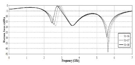
Figure 8. Comparison of Return Loss by Changing the Parameter S1
A compact size novel printed monopole antenna for WiMAX and WLAN applications is proposed in this paper. The required tri-band features are obtained through the specified design approach. This antenna has high gain (2.81 dBi (2.20-2.53 GHz), 2.65 dBi (3.09-4.24 GHz) and 4.38 dBi (5.03-5.89 GHz)), better bandwidth (0.33 GHz (2.20-2.53 GHz), 1.15 GHz (3.09-4.24 GHz) and 0.86 GHz (5.03-5.89 GHz)), improved efficiency and good return loss required for use of antenna in practical applications. The performance of antenna was also studied by changing the variable dimensions of the antenna.