Figure1(a). U-slot patch antenna
In this paper, a single layer wideband, probe fed modified U-slot microstrip patch antenna is designed for four-band communication system. The proposed antenna has impedance bandwidth of 28.57%(1.2 -1.4 GHz), 14.28%(2.6-3.03 GHz), 5.12%(5.7-6.05 GHz) and 8.9%(7.5-8.2 GHz) at center frequency 1.4 GHz, 2.8 GHz, 5.85 GHz, 7.85 GHz, with gain of 4dB, 10.4dB, 6.1dB, and 10dB. High gain of 10.4dB and 10dB is achieved at center frequency 2.8GHz and 7.85GHz respectively which is applicable for radar application and satellite application. The proposed antenna is designed on a single layer substrate Arlon AD250A with defected ground plane. Antenna is designed and simulated using HFSS v13 software.
Microstrip patch antennas are very popular in wireless communication because of its features such as the planar configuration, low profile, conformal to host platform, compatibility with monolithic microwave integrated circuits (MMICs). Another advantages of microstrip patch antennas are its low cost, ease of fabrication and installation. However, microstrip antennas have narrow impedance bandwidth problem, which can be improved by using different techniques, which include increasing patch height over ground plane, multilayer structure and use of low permittivity substrate [1].
U-slot antenna was first introduced by Huynh and Lee in 1995 [2]. After that, the design has been studied by many researchers. It is shown that U-slot patch can provide wide bandwidth more than 30% for air substrate and more than 20% for microwave substrate[3]-[9]. In paper [4],[5], a new approach is introduced to design dual-band and tripleband antenna. It is shown that by using L-probe feeding technique and cutting multiple U-slots in rectangular patch, notches are introduced which results in multi-band operation [4].In [6], a single layer, single patch four band u- slot antenna is designed by cutting four asymmetric u-slots. A pentaband patch antenna is designed with inverted U-slot and a coupled C-slot for Satellite Radio Broadcast Service (SRBS) and mobile services [9].
In this paper, our approach is to design a modified U-slot loaded single layer microstrip patch antenna with defected ground structure. We are using single U-slot with two rectangular slots instead of using multiple U-slots which can be use for multiband purpose. This multiband antenna is designed with the feeding technique coaxial probe feeding. The proposed antenna has been designed and simulated in HFSS v13 software, and return loss, radiation pattern and gain results are shown.
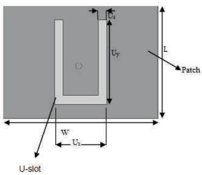
Figure 1(a) shows the basic geometry U-slot probe fed patch antenna taken from[10], in which length is L and width is W. The length of U slot is Ux , width is Uy and thickness of U-slot is Ua.
Figure1(a). U-slot patch antenna
The proposed antenna is modified version of above antenna. Proposed U-slot antenna is designed on a single layer substrate Arlon AD250A (ɛr = 2.5) of thickness h = 1.6 mm which is placed on the ground plane of size 71 mm × 52 mm. Arlon AD250A has low dielectric constant and it has very low loss and high efficiency. The proposed antenna provide multi-band characteristic. Figure 1(b) shows the proposed antenna which is designed by adding two more rectangular shaped slots in U-slot. The added rectangular slot's dimension is 2 mm × 2 mm. Another rectangular slot has dimension of 12mm × 1mm. To achieve multiband characteristics of antenna, defected ground plane is used. For that a rectangular slot of dimension 5mm x 20mm is cut in the ground. This defected ground plane provides a high gain multiband result with good return loss. Defected ground plane in proposed antenna is shown in Figure 1(e). Feeding technique used in the proposed antenna is coaxial probe feed in which core of radius 0.7mm is used. Coaxial probe feeding is shown in side view of antenna in Figure 1(c). Benefit of using coaxial probe feeding is that the position of feeding point can be anywhere of patch unlike other feeding, therefore, it is easy to use. Top view of the proposed antenna is shown in Figure 1(d). The dimensions are shown in Table 1 below.
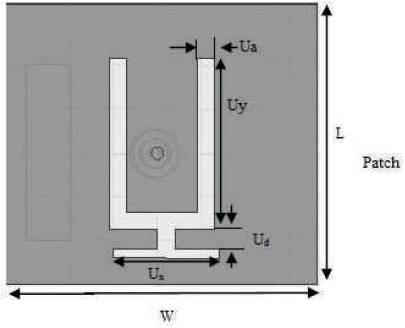
Figure1(b). Proposed U-slot patch antenna
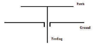
Figure 1(c). Side view of U-slot patch antenna
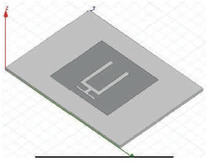
Figure 1(d). U-slot antenna designed in HFSS
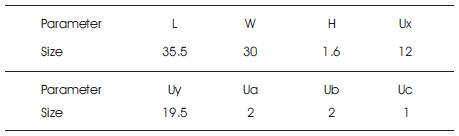
Table 1. Dimention of the Proposed Antennas (Unit: MM)
Ground Plane: 71mm X 52mm
Substrate: Thickness=1.6mm, Ɛr = 2.5
Size of Probe= 0.7mm
The antennas are designed and simulated using HFSS v13 software. The simulated return loss for the antenna is shown in Figure 2(a). The proposed antenna provides four frequency bands characteristics. Band 1 covers frequency band from 1.2 GHz to 1.6 GHz which have 28.57 % of bandwidth. Band 2 covers from 2.6 GHz to 3.03 GHz which have 14.28% impedance bandwidth. Another band is from 5.7 GHz to 6.05 GHz having 5.12% of impedance bandwidth. The last band covers 8.9% impedance bandwidth from 7.5 GHz to 8.2 GHz. The results are mentioned in Table 2 which shows all the four bands with its % impedance bandwidth. Figure 2(b) shows the gain vs. frequency graph which shows high gain obtained is 10.4 dBi at frequency 2.8 GHz which is quite good. Another high gain of 10dBi is obtained at frequency 7.85 GHz. Figure 2(c) shows 3D radiation pattern of proposed antenna and 2D radiation pattern is shown in Figure 2(d). Table 2 shows all frequency band obtained with % impedance bandwidth (all in GHz).
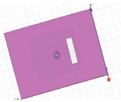
Figure 1(e). Defected ground plane in HFSS
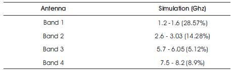
Table 2. Frequency Bands with % Impedance Bandwidth (Unit: GHz)
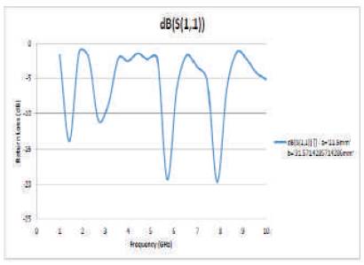
Figure 2(a). Simulated return loss vs frequency graph
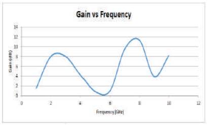
Figure 2(b). Simulated gain vs frequency graph
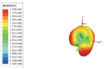
Figure 2(c). Simulated 3D radiation pattern
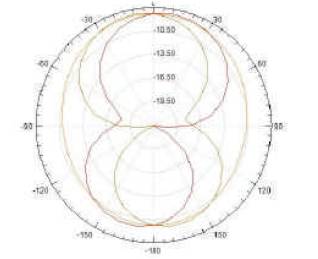
Figure 2(d). Simulated 2D radiation pattern
In this paper, we designed a modified U-slot microstrip patch antenna in addition with two small rectangular slots and defected ground plane for introducing various notch in frequency band. Introducing defect in ground plane provides enhancement in bandwidth, better return loss and multiband characteristics. From Table 2, frequency ranges of various bands are shown, band 1 (1.2GHz-1.6 GHz) is in L-band and it can be used for the application of Gps and also for satellite mobile. Band 2(2.6GHz-3.03GHz) is in S-band and this band can be use for weather radar application. Band 3 (5.7GHz-6.05GHz) and band 4 (7.5GHz-8.2GHz) lies in C-band of frequency spectrum and these bands can be use for satellite communication. The proposed antenna has following advantage: (1) the antenna used simple feeding technique. (2) Antenna has single layer structure. (3) Structure of designed antenna is simple. (4) Gain of the proposed antenna is high. The measured impedance bandwidth -10 dB of reflection coefficient of the four bands are 28.57% (1.2GHz-1.6Ghz), 14.28% (2.6GHz-3.03GHz), 5.12% (2.6GHz-3.03GHz), and 8,9% (7.5GHz-8.2GHz).2D and 3D radiation pattern plotted for theta, phi vs. frequency parameter is shown in Figure 2(c) and Figure 2(d) which is quite good. Gain obtained is high for 2.8 GHz which lies in band1 and 7.85 GHz which lies in band2 frequency band which can be used for radar and satellite communication.
U-slot microstrip patch antenna is well known for its wide band characteristic. There are many types of single and multiple U-slots presented in past papers for single band and multiband purpose. In this paper, we successfully applied modified type of U-slot with defected ground plane to achieve four frequency band characteristics with high gain. Its structure is simple from past structures and gives better results. The proposed antenna uses simple feeding technique and provide enhancement in gain, return loss and bandwidth which is useful for various wireless application.