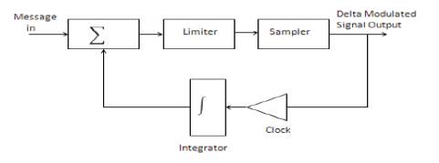
Figure 1. Basic Delta Modulation
Two receiver architectures for equalization of multi-h continuous phase modulation (CPM) are presented. In the first technique, the receiver front end is a matched-filter bank, which is obtained from Laurent decomposition of the signal. In the circulant-matrix model, samples of the matched filter are used to perform the equalization in frequency domain. The second technique employs a receiver with a simple front end consisting of a low-pass filter and a fractional sampler. Acirculant matrix model for the latter approach is devised, which relates the Laurent pseudo-symbols to each polyphase component at the output of the sampler. In this paper, delta modulation can simulate both analog and digital signals, during reception the noise will be removed by using Gaussian filter. In this method, turbo coding is used to increase the data rate in mobile communication.
Channel models are important for assessing the performance of modulation, equalization, and coding techniques on real channels. Channel models are usually categorized as either “narrowband” or “wideband.” Narrowband channel models are appropriate for situations where the signal bandwidth is much less than the coherence bandwidth of the multipath fading process [1, 14]. Continuous phase modulation (CPM), due to its spectrum and distance properties along with the constant envelope feature, is attractive for digital communications, especially in satellite and mobile communications. However, the implementation of the optimum coherent maximum-likelihood sequence detection (MLSD) receiver is, in general, very complicated, except for some simple CPM schemes such as the minimum phase-shift (MSK) type where the modulation index h is 1/2. The MLSD CPM receiver consists of a bank of analog matched filters followed by a trellis decoder using the Viterbi algorithm. The implementation complexity is due to the size of the matched filter bank and to the large number of states in the trellis, especially for non-binary and partial response schemes. In general, the more bandwidth and power efficient the scheme is, the greater the filter bank size and the number of states needed. This complexity, especially the filter bank size, prohibits their practical use. Considerable research has been directed to find suboptimum receivers with the objective of reducing the size of the matched filter bank and the number of trellis states with which the receiver needs to deal with. For the latter problem, it has been shown that whatever the number of the trellis states is, only a small part needs attention from the trellis decoder to achieve the error performance of the Viterbi algorithm, at least in a good channel. So, the goal of reducing the size of the filter bank can be achieved by trying to find a subspace of the transmitter space, with a smaller dimension but close in some sense to the original one. The performance loss of the receiver constructed from this subspace, which will be called receiver signal space, should be small [19]. There are two basic approaches to an FDE-based receiver design proposed previously for single-h CPM suffering from inter-symbol interference (ISI); one that has a MF bank front end and the other that utilizes a single low pass filter followed by fractional sampling. Short range wireless links will soon be anticipated to deliver bit rates of over 2 Gbits/s. Worldwide recent regulation assigned a 3 GHz or wider frequency band at 60 GHz to this kind of applications. A maximum likelihood (ML) CPM receiver in additive white Gaussian noise (AWGN) based on the Laurent decomposition contain a Viterbi decoder which makes use of the correlation properties of the LPs and PCs to perform ML sequence detection (MLSD) of the sent symbols power supply constraints, size, weight, and force the use of fully saturated, nonlinear RF power amplifiers [3]. As suited, the search for more bandwidth-efficient waveforms has been restricted to constant envelope waveforms. Two FDE receiver architectures are proposed for multi-h CPM; one that uses a MF front end and the other that uses a single low-pass filter followed by a sampler. For both schemes, the authors show that the sampled output of the receiver filter(s) satisfies a circulant matrix model for general mulit-h CPM waveforms given that the transmitted signal is cyclic for the duration of the block. The reduction in the complexity of the MF-based receiver is proposed by dropping the MFs and the FDE branches corresponding to low-energy Laurent pulses [2,4]. It is observed that the loss in performance is acceptable even when a few significant branches are considered. Similarly, complexity reduction can be obtained for sampling based (SF-based) approach by truncating the auto-correlation matrix of the multi-h CPM signal. Simulation results are presented for the IRIG-106 Tier- 2 dual-h CPM waveform [11].
Continuous phase modulation (CPM) represents a family of non-linear coded modulation schemes characterized by a constant envelope and continuity of the phase [1]. Modern aeronautical devices host an increasing number of sensors, which can transmit flight testing data to the ground station. However, this increased data transfer requires more bandwidth making the behavior of the aeronautical channel increasingly frequency-selective [5]. MMSE equalization theory in the FD for CPM signals has been presented in a unified framework. Conventional linear/decision feedback and turbo linear equalization algorithms processing two samples per channel symbol have been derived. Numerical results for binary 3-RC formats show that conventional FD equalization algorithms can offer excellent error performance at the price of a limited computational complexity [16]. To attain desirable detection efficiency, two different 32-state configurations were found to function within 0.05 dB of optimal and two different 16-state configurations were found to function within 0.80 dB of optimal and an 8-state configuration was found to function within 1.05 dB of optimal. The analysis and simulation results prove that to achieve a given state complexity, proper combination of two or more complexity-reducing techniques outperforms the use of a single complexity-reducing technique. It has been shown that there are two 32-state detectors whose loss in detection efficiency is less than 0.05 dB; two 16-state detectors whose loss in detection efficiency is less than 1 dB; and one 8-state detector whose loss in detection efficiency just greater than 1 dB[13]. A new polyphase matrix model, suitable for any block-based CPM system. Simulation results in a 60 GHz environment show that our reduced complexity MMSE equalizer outperforms the state of the art linear MMSE receiver for large modulation indices, while it performs only slightly inferior for small ones. Calculating the MMSE equalizer required the inversion of a no diagonal matrix. This defeats the primary objective of FDE, namely low-complexity equalization requiring only inversion of diagonal matrices in the frequency domain[17].
De Jager (1952) hit on an idea for dispensing with the need for a sample and hold circuit. If the system was producing the desired output, then this output could be sent back to the input and the two analog signals compared in a comparator. The output is a delayed version of the input, and so the comparison is in effect that of the current bit with the previous bit, as required by the delta modulation principle [6,9].
Figure 1 shows that the system is in the form of a feedback loop. This means that its operation is not necessarily obvious, and its analysis non-trivial.
Figure 1. Basic Delta Modulation
The system is a continuous time to discrete time converter. In fact, it is a form of analog to digital converter, and is the starting point from which more sophisticated delta modulators can be developed [15]. The sampler block is clocked. This is the delta modulated signal, the waveform of which is shown in Figure 2. It is fed back, in a feedback loop, via an integrator, to a summer.
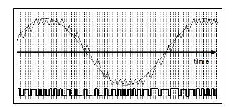
Figure 2. Delta modulation wave form
The integrator output is a saw tooth-like waveform, also illustrated in Figure 2. It is shown overlaid upon the message, of which it is an approximation.
Figure 2 shows that the saw tooth waveform is subtracted from the message, also connected to the summer, and the difference of an error signal is the signal appearing at the summer output [12].
An amplifier is used in the feedback loop. This controls the loop gain. In practice, it may be a separate amplifier, part of the integrator, or within the summer. It is used to control the size of the 'teeth' of the saw tooth waveform, in conjunction with the integrator time constant. When analyzing the block diagram of Figure 1, it is convenient to think of the summer having unity gain between both inputs and the output. The message comes in at fixed amplitude.
The signal from the integrator, which is a saw tooth approximation to the message, is adjusted with the amplifier to match it as closely as possible [18, 20].
When compared to earlier A/D modulation techniques, delta modulation provides a higher SNR. Signal-to-Noise Ratio is the ratio of the strength between data and noise within a transmitted signal, and it is calculated in the units of decibels (db). In data communication, the signal power is inversely proportional to noise power, which shows that higher signal power results in higher SNR, which is the sign of increased signal strength and reliability. The Other common A/D modulation techniques like PCM (pulse code modulation) and DPCM (differential pulse code modulation) are having a relatively lower SNR as compared to delta modulation [8].
Delta modulation offers a significant benefit of lower channel bandwidth consumption. Bandwidth of a channel is the range of frequencies allowed for a signal to employ for transmitting its data [7]. This feature is very crucial in data communications, and increase in bandwidth directly increases cost and management efforts of a transmission network. For this reason, delta modulation provides a benefit of lower bandwidth consumption, which makes the process of data communications more cost effective and simplistic [10].
In Figure 3, the operation of a delta modulator is to periodically sample the input message, to make a comparison of the current sample with that preceding it, and to output a single bit which indicates the sign of the difference between the two samples. This principle would require a sample-and-hold type circuit.
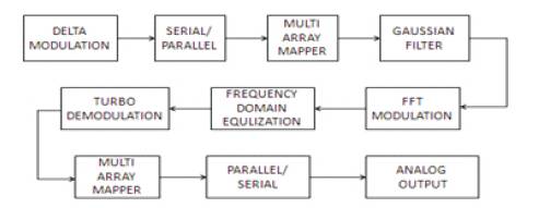
Figure 3. Proposed Block Diagram Frequency Domain Equalization
Gaussian filters are used in GSM because of their advantages in carrier power, occupied bandwidth and symbol-clock recovery. The Gaussian filter is a Gaussian shape in both the time and frequency domains.
The Viterbi algorithm is a programming algorithm for detecting these sequence of concealed states called the Viterbi path that results in a sequence of observed events, in the context of Markov information sources and hidden Markov models.
The algorithm has universal application in decoding the convolution codes which is used in both CDMA and GSM digital cellular, dial-up modems, satellite, deep-space communications, and 802.11 wireless LANs[21]. It is used in speech synthesis, speech recognition, divarication, keyword spotting, computational linguistics, and bioinformatics
It is also feasible to approach the Shannon limit by using a block code with large block length or a convolution code with a large constraint length, hypothetically. But this approach is not practical due to the processing power required to decode such long codes. By using recursive coders and iterative soft decoders, this limitation can be overcome by Turbo codes [22,23]. The recursive coder makes convolution codes with short constraint length which appears to be block codes with a large block length, and the iterative soft decoder progressively improves the estimate of the received message.
The simulation results of the frequency domain modulation method using delta modulation are presented. Only one signal is used in the existing system; it needs more signals to establish itself and so it is considered that over noise will occur. To overcome those drawbacks, delta modulation is used.
Figure 4 shows the simulation tool used for processing the input, both analog and digital bits is done using VERILOG. The MODELSIM is used for simulation. The version of MODELSIM is 6.5c. The inputs bits are get simulated to produce the output by the analog waveform. Figure 5 shows the hardware module.
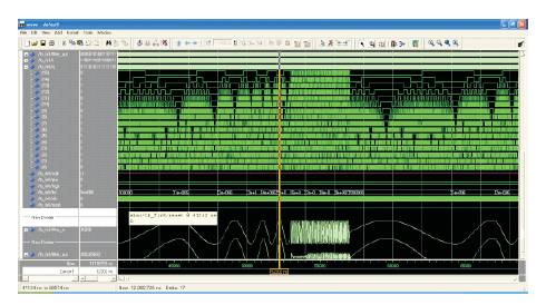
Figure 4. Simulation result for both analog and digital signal
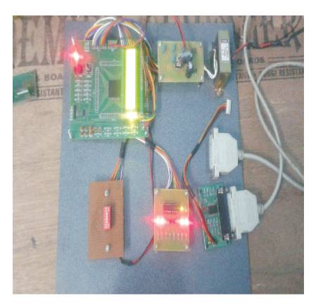
Figure 5. Hardware module
The computational complexity of each of these architectures is then analyzed, and results are reported in terms of the number of front end filters and the number of floating points operations (FLOPs) required for various components of the receiver. Several methods have been proposed to achieve further reduction in receiver complexity, e.g., by ignoring low-energy Laurent pulses in the MF-bank, by using a reduced-state demodulator, or by truncating signal correlation while computing the equalizer. It is suggested that by combining these methods in a judicious manner, it is possible to get a substantial reduction in the overall receiver complexity without sacrificing too much performance.
The proposed system using turbo algorithm is to optimize the performance in the receiver. In future, the simulation model designed for the delta modulation system is utilized for the hardware implementation. It is hoped that the proposed delta modulation using turbo algorithm provides more reliability and also increase the data rate in mobile communication.