Introduction
The major subsystems of the power plant include the boiler, turbine coupled with the generator. The steam output from the boiler unit is the input to the turbine and the steam pressure helps in the rotation of the turbine shaft. This mechanical output from the turbine helps in the rotation of the generator, which is coupled with the turbine unit, thereby converting this mechanical energy to electrical output. Power generated is further fed to the power station or the grid station and effectively transmitted to the load. Information on the collected data are to be transmitted one place to another, like from the field to the control room, for efficient monitoring and control over the subsystems of the power plant. Many of the industries still use wired technology for transmission of these data. Coaxial cables or twisted pair of cables is the basic medium of transmission under wired technology. Wired data transmission has its own advantages like low signal losses, much reliable as there is no signal theft, high speed, high life expectancy. Inspite of its advantages, the disadvantage lies in the installation as well as the maintenance of the wired cables as it is affected by weather conditions and also the noise generated by the mechanical and magnetic links.
Wireless transmission supports more number of user data and also a safe and secure exchange of data is possible through wireless technology. The basic analog modulation techniques are involved in transmitting the data which has the disadvantages of secure transmission, low noise immunity, difficult to design as the hardware is not flexible, and is Low Quality of Service (QoS). Nowadays digital modulation plays a vital role in transmission of data in many of the industries. When more than one data is to be transmitted effectively at a same time, the multiple access techniques are a boon and very helpful in data transmission. Code Division Multiple Access (CDMA) helps in transmission of multiple data at a time very effectively in a very safe and secure manner [5]. Each user data is assigned with a very specific code dedicated to it which is encoded and decoded at the transmitter and the receiver side respectively. Binary Phase Shift keying technique is the simplest form of phase modulation and is a two level modulation which uses a pair of signal to represent binary symbols 0 and 1. Data is spreaded and despreaded from the transmitter and the receiver respectively [5].
1. System Description
The input to the boiler is lignite, also known as brown coal, which is fed to the boiler with the help of conveyer belts as the medium of transportation from the mining area to the power plant. This lignite is burnt as a fuel to heat the feed water present inside the boiler drum. At a particular temperature this feed water is converted into steam which helps in the rotation of the turbine.
The general arrangements of the boiler, shown in Figure 1, are the natural circulation system comprising of single drum, non steaming economizer, membrane radiant water walls in a dry bottom furnace, reheaters, auxiliary fuel oil burners for firing light diesel oil, furnace oil, pulverized lignite firing units with beater wheel mills, balanced draught system with axial profile blading fans, regenerative air preheaters along with two steam coil air preheaters, electro static precipitators and wet ash disposal system. Air that is required for complete combustion is supplied by forced draught fans. Flue gases in the system enter from the top and leaves at the bottom, whereas air enters from the bottom and leaves at the top of the air preheaters. Each air preheater is well equipped with a steam soot blower.
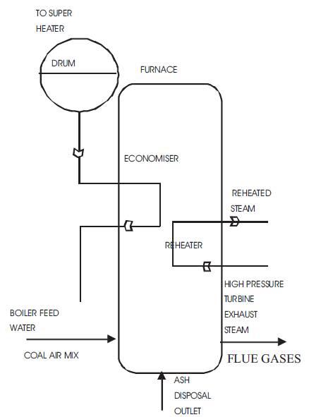
Figure 1. Flow Diagram of Boiler Unit
Boiler drum is the central unit of natural circulation evaporation system which helps in the separation of the steam water mixture formed in the boiler drum. The function of the economizer is to preheat the feed water before it enters the steam drum and also to recover some amount of heat from flue gases leaving the boiler. The preheater and reheater assemblies are horizontal banks and are supported by steam cooled hangers and safety valves are also provided at the boiler drum. The firing system is handled by the lignite handling system with lignite as the fuel. Lignite is drawn from the bunker and the plate belt feeders discharge the lignite into the conveyer belts which in turn feeds to the mills wherein the beater wheel mills are provided for pulverization. Fuel oil burners for firing diesel oil, furnace oil are also provided for the supply of light diesel oil with the help of pumps.
There are various parameters that are measured as input and output of/from the components of the boiler unit. These include Lignite Flow, Feed Water Flow, Steam Flow, Spray Flow of the Super-Heater and Re-heater, Temperature and Pressure of the Super-Heater and Re-heater, the O2 % content, the outputs of water soot blowers and steam soot blowers, Flue Gas temperature of the super-heater, economizer and the Induced draft fans, Lubricating oil flow, pressure and temperature.
2. DS-CDMA Transceiver
The block diagram of a DS-CDMA transceiver system is shown in Figure 2. The Lignite Flow (LF), Feed Water Flow (FWF), Steam Flow (SF), Super Heater Spray Flow (SSF) are the input data that are collected from the boiler unit of the power plant. These data are analog signals. They cannot be processed or transmitted in analog nature and hence they are converted to digital signals. This conversion is done using an analog to binary converter. This converts the input analog data to binary data for further transmission. The respective binary outputs for the input data are LFb, FWFb, SFb, SSFb. The binary output data are transmitted with the help of a DS-CDMA transmitter [3]. This transmitter multiplies each user input with a separate code which is very specific for each user. The outputs from all the users overlap and interfere with each other in the DS-CDMA transmitter. These combined transmitted signals that are spreaded together are received with the help of the DS-CDMA receiver by correlating the combined signal with the specific code dedicated to each user to differentiate them.
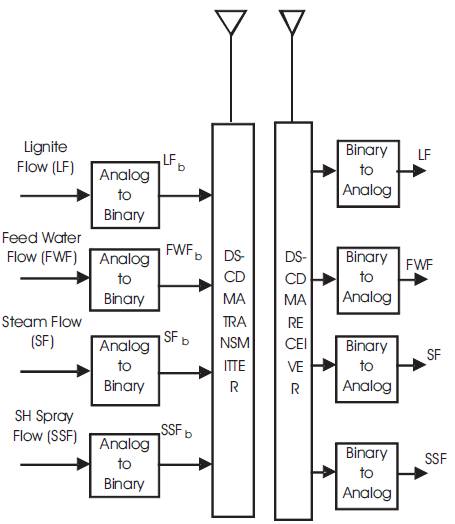
Figure 2. Block Diagram of DS-CDMA Transceiver
3. DS-CDMA Transmitter
The binary output data for the input data are LFb, FWFb, SFb, SSFb. In the DS-CDMA transmitter, LFb is multiplied with the gold code 1 sequence from the gold code generator [1]. The output is fed as an input to the BPSK modulator and the other input is provided with the help of the local oscillator. The spreaded sequence, LFS, of the binary input LFb is obtained at the end of the BPSK modulator. Similarly all the other three binary data are also multiplied with the respective gold code sequence from the gold code generator and fed to the BPSK modulator and their equivalent spreaded sequences FWFs, SFs, SSFs are obtained. The combined spreaded sequence is finally transmitted through the channel. The blocks of the transmitter are shown in Figure 3.
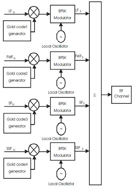
Figure 3: Block diagram of DS-CDMA Transmitter
4. DS-CDMA Receiver
The DS-CDMA Receiver has the inverse procedure to obtain the final despreaded sequence. The block diagram of the receiver in Figure 4 clearly explains the procedure. The spreaded sequence received from the channel is demodulated using a BPSK demodulator and the demodulated output is again multiplied with the gold code sequence which is specific to each user. All the four binary data are despreaded at the receiver side [2].
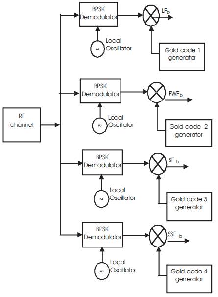
Figure 4. Block diagram of DS-CDMA Receiver
5. Results
The output results were obtained by considering four input parameters. Length of each parameter is 8 bits and the length of gold code sequence is 15 bits. The bit time for each bit representation is 10 and the simulation is performed using Matlab software to obtain the results.
The real-time sample data are observed and considered and four input parameter values are tabulated for a set of ten sample values as in Table 1. The analog data are converted to digital form and transmitted to the receiver side when both spreading and despreading takes place.
The original bit sequence for all the four input parameters are shown in Figure 5. Each parameter is represented by 8 bits with bit time being 10. The gold code sequence for each input parameter from the gold code generator is obtained as shown in Figure 6. XOR operation is performed on the input bit sequence and the gold code sequence to obtain the combined spreaded sequence of length 480 which is shown in Figure 7. The transmitted spreaded sequence is despreaded at the receiver section to obtain the original bit sequence of the input parameters and the simulation result is as obtained using Matlab [4] as shown in Figure 8.
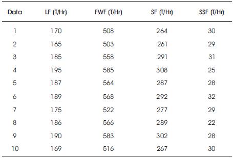
Table 1. Sample Data values
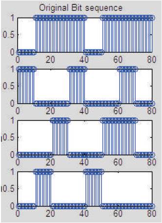
Figure 5. Original bit sequence of input parameters
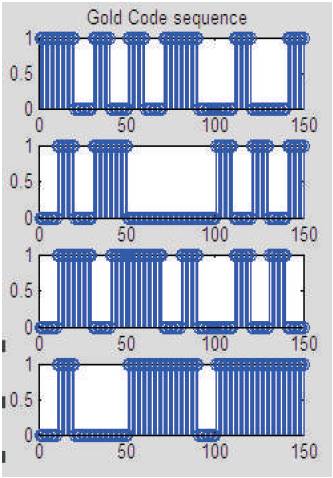
Figure 6. Gold Code sequence from generator
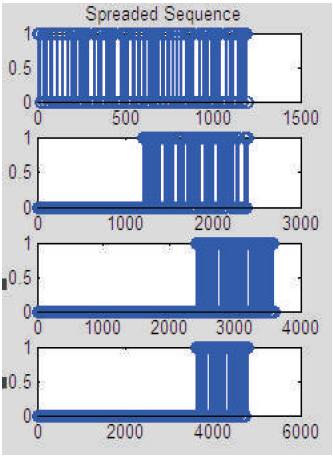
Figure 7. Spreaded Sequence
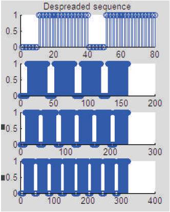
Figure 8. Despreaded Sequence
Conclusion
Probability of BER Error log10 (Pb) Vs SNR per bit Eb/N0 were calculated for several digital modulation techniques. Simulation results shown in Figure 9 infer that the BPSK modulation technique has better BER when compared to the other methods.
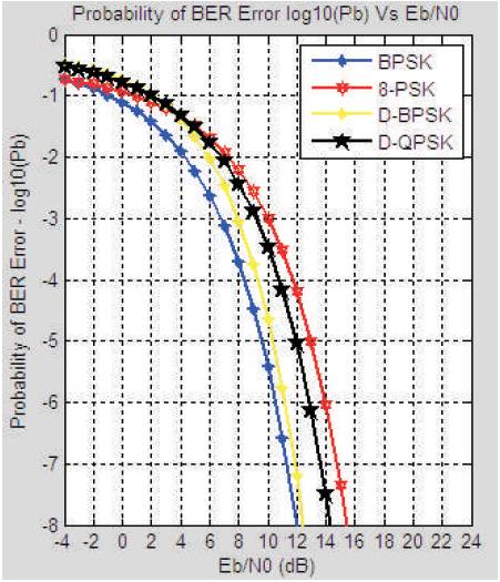
Figure 9. BER Error Vs Eb/N0